
記住我


The study presented the performance of the robot grid system for parallel needle insertion with support to angulate needle insertion path to accommodate targeting the lesion in various position. Two sets of test were conducted to assess the accuracy of the system and its ability to maintain needle orientation.
The system accuracy test result revealed that the robot can uphold needle insertion accuracy across different target depths and orientation. IRE treatment typically utilized to address tumor with size ranging from 1 to 7 cm as outlined by Moir et al. [14]. The robot is expected to position the needle with an error of less than \(\pm \,\hbox \) to adequately cover the minimum tumor size. The accuracy test confirms that the robot meets this requirement, with a maximum error the robot can meet the requirement with average error of \(2.71\pm 0.68\) mm.
The result of needle alignment test demonstrated that the proposed robotic grid system effectively maintains parallelism during needle insertion with minimal deviation, even when performed on different subgrids. According to the IRE protocol, a maximum angulation of \(10^\) is permissible to ensure a homogeneous distribution of the electric field [15]. Additionally, in our previously study [16], it was found that deviation of needle orientation exceeding 5\(^\) can significantly impact the outcome of IRE procedures. In this case, the robot can manage multiple needle insertion with deviation generally below 2\(^\), which is within an acceptable range for IRE procedure.
Fig. 7
Illustration of needle position inside the hole grid, where a needle with a straight trajectory and b needle deviation due to the space presence in the hole grid
In an ideal case, performing needle insertion using the robot grid would give precise needle placement. However, the potential sources of error in the experimental procedure may come from a variety factors. It is including but not limited to: inaccuracies in the manufacturing of the robotic components, the rigidity of the robot design, registration errors between the robotic coordinates and the electromagnetic tracker, and potential bending of the needle after repetitive test. Based on our observation during the experiment, it revealed that the another factor of error is coming from the design of the grid hole used in the robot system. To demonstrate this phenomenon, an illustration of the needle positions within the grid hole is shown in Fig. 7.
Ideally, a needle will follow a straight trajectory when inserted through a hole (Fig. 7a). However, due to limitations encountered during manufacturing of the grid components, a certain degree of space may be present within the hole grid, which may cause the needle to deviate from its intended trajectory, as demonstrated in Fig. 7b. In such scenario, the maximum deviation of the needle can be quantified by calculating the values of \(x_1\), \(x_2\), \(x_3\), and \(x_4\).
Assuming \(\theta \) is small enough, where \(\cos \theta \approx 1\), and knowing the dimension of \(d_\text \) and \(d_\text \) as the diameter of the needle and the grid, the value of \(x_1\), \(x_2\) and \(x_3\) are as follows:
$$\begin x_1&\approx d_\text \end$$
(2)
$$\begin x_2&\approx \frac} \end$$
(3)
$$\begin x_3&= d_\text - x_1 \end$$
(4)
Furthermore, with \(h_\text \) as the thickness of the grid and \(h_\text \) as the depth of the target, \(x_4\) can be calculated using the extrapolation made by the needle:
$$\begin x_4&= \frac}}(d_\text -d_\text ) - \frac} \end$$
(5)
Finally, needle deviation (\(e_\text \)) can be calculated by substituting the value of \(x_2\) and \(x_4\):
$$\begin e_\text &= x_2 + x_4 \nonumber \\&= \left( \frac}} -\frac\right) (d_\text - d_\text ) \end$$
(6)
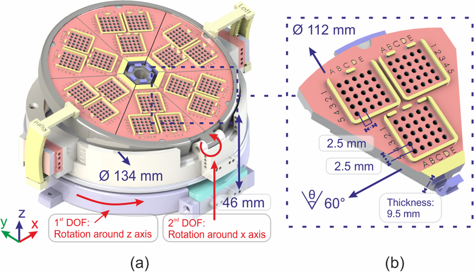
In the design of our robot, the grid dimensions, \(d_\text \) and \(h_\text \), are equal to 1.5 mm and 9.5 mm, respectively. An offset of 43.3 mm, which represent the distance from the top surface of the grid to the reference point on the robot’s base, must be taken into account when determining the target depth, \(h_\text \). Meanwhile, for the needle dimension, the Aurora 5-DOF needle has a diameter of 1.05 mm. By utilizing these values, we can predict the maximum deviation that may occur to the needle when targeting specific position at various depths.
The impact of needle deviation caused by clearance in the grid hole is clearly visible in the result of needle alignment test. When no rotation is applied to the robot, the deviation across all subgrids is relatively similar. However, when a large orientation is applied, the insertion depth varies between subgrids located near the axis of rotation in the x-axis and those located further away. As a result, subgrids 1 and 6, which are located at the farthest distance from the axis of rotation, have a longer distance to reach the target position, leading to higher deviation in the needle’s orientation compared to other subgrids.
The results of the experiments have indicated a clear need for improvement in the design of the grid system, particularly regarding the clearance of the grid holes. Further studies should concentrate on exploring fabrication techniques that can produce a tighter grid for the robot system, which has been demonstrated to improve accuracy, as reported by McGill et al.[17]. It is also crucial to minimize the distance between the device and the skin surface to decrease deviation error. This is supported by the Eq. 6 that shows that \(h_\text \) contributes to needle deviation.
Given that the robot was fabricated using non-metallic, non-magnetic, and non-conductive materials, it is necessary to assess its compatibility within the MRI environment. This can be done by evaluating the robot’s performance under MRI guidance and determining the effect of the robot’s presence on MR image quality. Additionally, incorporating MR-visible markers into the robot’s design is crucial for facilitating the alignment of the device’s coordinate system with the MRI’s coordinate system, thereby improving the accuracy of the registration process.
Another crucial aspect that needs attention is the metric used to evaluate the performance of the robot. The current study focuses on the accuracy and precision of the proposed robot in meeting various requirements reported in the literature. However, for the next clinical study, additional metrics are necessary. These include assessing the duration of installation and conducting experiments, as well as the training time required for the operator. External factor such as patient motion and their impact on the robot accuracy should also be considered. Furthermore, acceptance by the clinical community can be evaluated through questionnaires and interviews to gain insight into translating clinical requirements into robot specifications.
Finally, it is crucial to note that the current device is specifically designed for scenarios requiring multiple needles to be inserted in the same orientation around the target tissue. As such, this study can be extended by developing a path planning algorithm that provides automatic suggestions regarding the number of needles, position of needles, and insertion angle, taking into account the patient anatomy, the size and location of the tumor. However, in cases where individual needle adjustments are required, such as to avoid critical structures, a custom design of the subgrid can be implemented to address such cases. Nevertheless, it is preferable to utilize a more complex system that allows adjustment to each needle configuration, even if it extends the overall procedure time.
留言 (0)