
記住我
Noninvasive cortical stimulation using magnetic fields (MF) was first described in 1985.3 Based on Faraday law, MF induces activity in cortical neurons through a single transcranial magnetic pulse. Technical improvements in the 1990s, notably cooling systems, allowed transcranial magnetic stimulation (TMS) to become repetitive (rTMS) and hence be applied iteratively.
In the past 2 decades, rTMS has been increasingly used to relieve pain1,17,29 or to alleviate drug-resistant depression.5,12 For pain treatment, the main validated target is the contralateral primary motor cortex (M1), which was also the brain target historically used for invasive (epidural) electrical stimulation.14,25,37 The main limitation in these—magnetic or electrical—neuromodulations of M1 is that only half of the patients had an effective pain relief. Therefore, future research on neuromodulation aims to enhance the effects on M1 and to test other brain targets such as the secondary somatosensory (SII) cortex, midcingulate cortex (MCC), posterior insula (PI), anterior insula (AI), and dorsolateral prefrontal (DLPFC) cortex as promising sites for pain relief.4,8,13,21
For both invasive and noninvasive procedures, stimulation of the primary motor cortex has the advantage over other cortical areas of having a functional landmark allowing to properly set up the neuromodulation device. The observation of motor responses induced by the stimulation or the recording of motor-evoked potentials (MEPs) demonstrates an effective cortical stimulation of motor neurons, and this motor output is the guarantee of an adequate positioning of the stimulation device. The setting of TMS based on evoked potentials and/or neuronavigated procedure with the individual's anatomical scan is used when targeting “noneloquent” brain areas (ie, with no-motor responses), but the effective dose delivered is poorly estimated. Targeting deep brain areas in noninvasive neuromodulation requires at least an estimation of the MF decay as a function of distance from the coil.
Several studies have described the effects of magnetic pulses over neuronal activation in animal models.2,22 Mathematical simulations of MF interactions30,33,39 have emphasized the impact of bioelectrical characteristics of cranial tissues and brain layers on magnetic field intensity and distribution. Although the magnetic field distribution has been the subject of considerable research, most of the studies were based on computational models and rarely investigated in vivo preparations.20–24 To the best of our knowledge, only one study reported the electric field produced by a single pulse of TMS recorded with intracranial deep electrodes in an epileptic patient, with an estimate of the corresponding magnetic field.25 This case report was limited by both the static position of the electrode and the need to stimulate with a very small intensity (7% of the generator output). It has not been replicated so far because of the risks of epileptic seizure or brain damage by heating ferromagnetic components.18
To provide more comprehensive data on MF decay during TMS in real situations, we report and compare here recordings of MF in both the air and human postmortem (cadaver) models. Our findings provide a framework to choose the TMS intensity to deliver a proper MF in deep brain targets.
2. Methods 2.1. Stimulation and recording equipmentIn a first experiment, MF was generated through a common flat butterfly coil (Cool-B65 coil, Magventure) and a MAGPRO-X100 generator for records in the air and in postmortem heads. Because another (angulated) coil may be used in clinical practice to reach deep regions such as the motor representation of lower limb, in a second experiment, the MF was generated with a cone-shaped butterfly coil (Cool-DB80, Magventure) that delivered biphasic pulses. Its attenuation was also measured in the air, but not in the cadaver.
Recordings of MF were performed using a dedicated magnetic probe (MAGPROBE-3D Magventure, Farum, Denmark) and a high-frequency oscilloscope (PicoScope 3000 series, St Neots, United Kingdom).
2.2. Postmortem modelPostmortem specimens were collected by the laboratories of anatomy at the Faculty of Medicine—Université Claude Bernard Lyon1 (n = 8) and at the Faculty of Medicine Jacques Lisfranc—Université Jean Monnet Saint-Etienne (n = 2). Specimens came from persons who gave their body to science for research purposes. Specimens with history of cranial pathology and/or surgery were excluded, and no obvious cranial abnormality was noted for each head. For each specimen, the demographic characteristics and morphometric parameters were collected. No embalming was used for the brain.
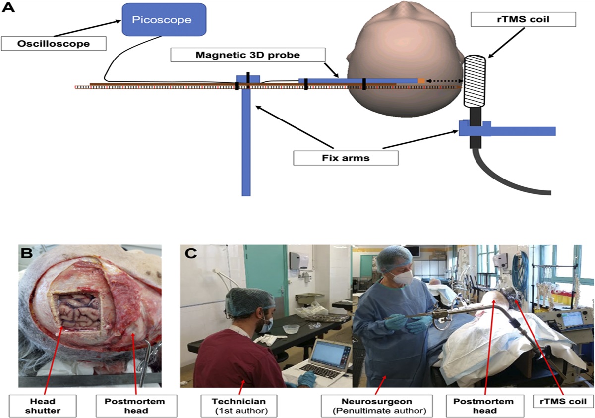
2.3. Recording of magnetic field in the airEach coil (Cool-B65 [flat] and Cool-DB80 [angulated]) was fixed vertically (ie, the handle of the coil was perpendicular to the floor) by a static nonmetallic clip. The recording probe was fixed on a graduated wooden stick that was kept perpendicular to the coil and that was aligned with the center of the coil (Fig. 1A). The probe extremity was adjusted to be in contact with the center of the coil for the first recording position in the air (Pa#1). It was displaced after each stimulus by steps of 5 mm along its supporting stick. The magnetic field was recorded at each position, from full contact with the coil (Pa#1) to a distance of 140 mm (Pa#28). Each TMS stimulus consisted of a single pulse at 100% of the power output of the stimulator. Five consecutive series of measures were conducted with each coil in the air.
 Figure 1.:
 (A) Experimental procedures: schematic representation of the recordings in the cadaver model with the coil placed on the right scalp and the probe introduced inside the postmortem brain from the left to the right side. The same procedure was applied in the air, from a maximal distance of 140 mm to the contact with the coil. (B) Cadaver head with the bone flap and (C) the real experimental conditions when using the cadaver model. rTMS, repetitive transcranial magnetic stimulation.
2.4. Recording of magnetic field in the postmortem modelCadavers were prepared by an experimented technician from the laboratory of anatomy, and the probe was manipulated by one of the authors (P.M., neurosurgeon). The Cool-B65 rTMS coil was fixed on the right side of the head (Fig. 1B). The center of the coil was adjusted to be in contact with the scalp, on the right temporal area, 2.5 cm above the earlobe in the frontal plane passing through the acoustic meatus (position T8 of the 10–20 EEG positioning system23). This position allowed us to be facing the sylvian sulcus and the posterior insular cortex.35,36 The probe fixed on the graduate stick was inserted through a bone flap performed in the left temporoparietal area and through a small incision of the underlying dura contralateral to the right temporal stimulation. This experimental procedure allowed performing a transversal (left to right) trajectory for the probe through the 2 hemispheres and avoiding the resistance of the falx cerebri. The graduated stick was driven by the neurosurgeon through the head until its extremity reached a contact with the bone facing the center of the coil (Fig. 1C).
The first recording position Pc#1 was always the contact with the brain at the cranial entrance—ie, at the farthest position relative to the stimulus. Then, recordings were made by moving forward the probe from the left to the right side, by steps of 5 mm until it contacted the dura mater and the skull from the inside on the left side, where the coil was placed. During all the recording procedure, the graduated stick that served as a guide for the probe was maintained static by a mechanical device (Yasargil autostatic arm from B Braun Medical). We measured the distance corresponding to the first (entrance of the head) and the last (contact with the contralateral skull) positions of the probe. Because of tissue accumulation at the end of the experiments, the probe's extremity could not exactly reach a bone contact, and thus, the distance occupied by this residual parenchymal tissue was measured. Finally, we measured the bone and the scalp thickness under the coil.
2.5. Data processing and analysisRaw data collected with the probe were in millivolts with the scale: 1V for 1.4 kilo-Tesla per second (kT/s). Raw data were processed using MATLAB software to correct the mean kT/s to T.
Statistical analysis was performed using GraphPad Prism (v.9). Outcomes are expressed as mean and 95% confidence intervals (CI), and appropriate effect sizes are systematically presented alongside P-values.
2.6. Feasibility to reach deep brain targetsTranscranial magnetic stimulation efficiency is related to the magnitude of the magnetic field to be delivered to the target. To treat patients with chronic pain, TMS intensity over the primary motor cortex is determined according to the patient's motor threshold (MT—ie, minimum intensity to induce a motor response by a single TMS stimulation). From a previous study conducted in our laboratory in 34 patients,28 we estimated the average minimal magnetic field capable of triggering a motor-evoked potential (MT) after stimulation of the healthy hemisphere. This average MT was 54% and was used here as the “reference” MT to reach a motor-evoked potential with the flat coil and to determine the required intensity to obtain the same MF for brain targets at different depth.
Using the participants' anatomical scans (3D T1-weighted MRIs—Siemens sequence; axial images acquired with voxel sizes between 0.938 and 1.0 mm), we determined the average depth of 6 clinically relevant brain targets,13 namely (1) the hand location in the primary motor cortex (M1; the center of the “omega-shaped” convolution within the central sulcus); (2) the posteroexternal part of the parietal operculum (S2); (3) the posterosuperior insula (PI, dorsal area of the anterior long gyrus, see Ref. 9); (4) the anterioventral part of insular sulcus (AI; insula pole); (5) the anterior midcingulate cortex (aMCC, rostral and pregenual area of the cingulate cortex, at a midpoint between the vertical line through the anterior commissure (VCA) and the genu of corpus callosum38); and (6) the dorsolateral prefrontal cortex (DLPFC, middle frontal gyrus corresponding to the lateral part of Brodmann areas 9 and 46, see Ref. 27).
Distance to the target (DTT) was defined as the minimal distance between the outer surface of the cortical target and the surface of the scalp.
We used MRIcron software (www.mricro.com), which provides a 3D surface rendering of the brain, to determine the individual coordinates (X, Y, Z) of the brain regions and the orthogonal coordinates of the scalp. Location of brain regions was defined based on an atlas of the human insula9 and the Human Connectome Project brain atlas.15 We used MATLAB scripts previously developed by our group to move from standardized space (MNI or Talairach) to individual space and define brain targets directly on the individual patient's anatomy (see Ref. 27 for more details).
The scalp-cortex distance was computed using the following formula: racine((Xscalp × voxel size − Xcortex × voxel size)^2 + (Yscalp × voxel size − Ycortex × voxel size)^2 + (Zscalp × voxel size − Zcortex × voxel size)^2). Scalp–cortex distances were averaged across subjects (±SD).
3. Results 3.1. Transmission on airFor the flat Cool-B65 coil, the maximum magnetic field was 0.88 T (95% CI: [0.86–0.90]), when the probe contacted the center of the coil. At 140 mm from the coil (farthest position), the field was measured at 0.0057 T (95% CI: [0.0056–0.0059]; Fig. 2A). The decay of the magnetic field with distance could be adequately fitted by a negative exponential curve with the following equation: F(x) = e(−0.048.x). 0.8650229 (x = depth). The model showed a decrease of magnetic field of >50% at 1.5 cm and >75% at 3 cm (Fig. 2B).
 Figure 2.:
 Magnetic field recordings of data in the air: (A) Average records with error bars (SD) for the flat coil (blue) and the angulated coil (orange) for a stimulation at 100% of power. (B) Fitting model corresponding to the flat coil (blue) and angulated coil (orange) for stimulations at 100% of maximal power, plus that obtained at 50% of maximal power (gray curve). The blue and orange horizontal lines represent the 20%, 50%, and 75% decrease thresholds when using the flat and angulated coils, respectively.
For the angulated coil (Cool-DB80), the maximum magnetic field was 0.77 T (95% CI: [0.73–0.81]) at the first position, when the probe contacted the center of the coil. At 140 mm from the coils, the field was measured at 0.00993T (95% CI: [0.0111–0.00873]; Fig. 2A). The magnetic field could be best fitted by a reverse logarithmic curve presenting the following equation: F(x) = e(−0.031.x). 0.810584 (x = depth). With this model, a decrease of magnetic strength of >50% was obtained at 2 cm and >75% at 4.5 cm (Fig. 2B).
3.2. Postmortem modelCadaver specimens were 7 females and 3 males, at 7.1 days postmortem on average (range 1–12 days). The thickness of the scalp and the bone was 4.78 mm (95% CI: [3.87–5.69]) and 7.67 mm (95% CI: [6.58–8.75]), respectively. The first position of the probe at the entrance of the probe in the head was at 135.7 mm from the coil on average (95% CI: [125.41–145.98]), and its last position, closest to the coil at the contralateral stop, was 17.45 mm (95% CI: [13.38–15.42]).
At the nearest intracerebral position, the (maximum) magnetic field was 0.34 T (95% CI: [0.285–0.39]). At the more distant position (entry in the skull contralateral to the coil), the magnetic field was measured at 0.0052 T (95% CI: [0.00441–0.00599], Fig. 3A). The magnetic field could be adequately fitted by a negative exponential function: F(x) = e(−0.0418.x). 0.6156972 (x = depth). This model predicted a decrease of magnetic field of >50% at 1.5 cm and >75% at 3 cm (Fig. 3B).
 Figure 3.:
 Magnetic field recordings in postmortem conditions measured in Tesla (T). (A) The 10 individual records with the mean decrease of the MF in red. (B) Here, the representation of the 2 mean curves of MF decay (error bars denote SD). The air model curve (blue) with the equation F(x) = e(−0.048.x) as a function of the distance. Also represented the different cortical targets on an anatomical MRI according to their mean depth in mm. (*) For both (A and B) figures, in the postmortem condition, the nearest position to the magnetic coil was not zero, but 17.5 mm on average because of tissue accumulation in front of probe and interposition of meninges skull and scalp.
3.3. Prediction of magnetic field strength at cortical targetsIn the air and cadaver models, the fitting models were not significantly different (P = 0.80; Fig. 3B). Thus, for simplification of the estimation, but also because of large anatomic variability between the targets, we used the equation of air transmission to compute the intensity of MF at targets.
The average depth of the 6 possible cortical targets (see Methods, Table 1 and Fig. 3B) ranged from a minimal distance of 28 ± 1.41 mm for the DLPFC to a maximum of 57.5 ± 0.71 mm for the aMCC. No significant difference was observed between males and females.
Table 1 - 1st column: depth of each cortical targets in mm; 2nd column: for each target, estimation of the magnetic field intensity (Tesla) produced by the classic flat coil after a stimulation over M1 target at the motor threshold (MT).
In brackets, the same results expressed as a % of the MT reaching the target. Third and fourth column: Each value refers to the output of the rTMS generator that would be necessary to induce an MF in the target equivalent to the MF measured in M1 after stimulation at the MT. In brackets, the same results expressed as a % of MT. Results are those measured in the postmortem brain for the classic flat coil (gray) and those extrapolated from the aerial conductions for the angulated coil (orange). All the measures presented here refer to an averaged output of rTMS generator set at the MT (54%) for a stimulation over M1 with the flat coil (see Methods).
ACC, anterior cingulate cortex; AI, anterior insula; DLPFC, dorsolateral prefrontal cortex; M1, primary motor cortex; PI, posterior insula; S2, secondary somatosensory cortex.
For the flat coil, the abacus in Table 1 provides the theoretical estimate of the magnetic field intensity delivered to each of the 6 targets if we stimulate at the reference MT (54%). Under such conditions, at M1, the magnetic field was estimated to be 0.12 T, whereas at the aMCC, the magnetic field would be of 0.032 T (ie, only 26% of the magnetic field delivered at M1). As shown in Table 1, the theoretical intensity of the rTMS generator needed to deliver a magnetic field equivalent to that of the motor cortex (=0.12 T) would rise from 54% of the rTMS generator power for M1 to 207% of maximal power of the rTMS generator for the aMCC. As another example, delivering a similar magnetic field to the posterior insula would require 108% of maximal power of the rTMS generator.
For the angulated coil D-B80, a similar abacus was constructed (Table 1). The generator output necessary to reach a magnetic field equivalent in intensity to those present in M1 at different targets is shown in Figure 4.
 Figure 4.:
 TMS intensities needed to be delivered at different cortical targets to obtain a magnetic field at a level equivalent to that used for motor threshold over M1. Blue and orange bars correspond to the flat and angulated coils, respectively. Values in percentage of maximum possible intensity of the device. ACC = anterior cingulate cortex; AI, anterior insula; DLPFC, dorsolateral prefrontal cortex; M1, primary motor cortex; PI, posterior insula; S2, secondary somatosensory cortex; TMS, transcranial magnetic stimulation.
For the flat coil, beyond >40 mm of depth (eg, for posterior insula and anterior cingulate cortices), the model finds a range of intensities impossible to be delivered by the rTMS stimulator (108% and 207%, respectively), whereas the angulated coil allows to stimulate the furthest target (Antérior Cingulate Cortex [ACC] = 57.1 mm) using reachable intensities with the rTMS stimulator (89%).
4. DiscussionThis study provides direct recordings of the magnetic field produced by transcranial magnetic stimulation in human ex vivo head models and allows for a direct comparison of MF transmission with that in the air. The finding of a similar decay (Fig. 3B) in the 2 environments was expected considering the magnetic properties within biological tissues.32 This work is useful to estimate the magnetic field intensity (or “dose”) delivered on a given brain target.
Based on the average motor threshold determined in 34 patients who received rTMS in our laboratory, the average distance between brain targets and their nearest scalp point, and the calculated equation decays, we could estimate the intensity needed to reach several intracranial targets, relative to intensity needed to obtain the motor threshold after stimulation of M1. Our results showed a rapid and important decrease of MF intensity with distance, with a > −30% drop at distances consistent with the S2 area (35 mm), −50% for the posterior insula (∼43.5 mm), and up to −75% for the aMCC (∼57 mm), when using a flat coil. Given such important decrease, it is highly unlikely that rTMS delivered at MT would be able to effectively stimulate these targets. A simple option to counterbalance this decay of magnetic field would be to increase the power of stimulation, but this alternative presents with both practical and clinical difficulties. As shown in Figure 4, the required adaptation of intensity is important and would require stimulation intensities far above the MT for a number of relatively deep targets such as the insula or ACC (Table 1), with the risk of triggering epileptic seizures.19 Our results also suggest that an angulated coil may be more appropriate for reaching deep targets without requiring excessive intensity increase (Table 1) and would represent a good alternative to a flat coil when stimulating targets located more than 40 mm from the surface. This is a finding in agreement with previous work based on mathematical modeling of electric fields induced by magnetic flux per surface unit (E = DΦ/Dt, Φ being the magnetic flux), which also reported the superiority of the angulated coil, compared with flat coils, in reaching deep targets (Deng et al.7). Deng et al.6 predicted a linear decay of MF when “the coil was large relative to the head,” which was the case in their modeling approach, but clearly not when using a real coil over real heads, as was the case in our experiments, which found a negative exponential decay.
Because rTMS of M1 is effective in around 50% of cases with intractable pain,12 targeting other cortical areas distant from the surface of the skull may become a new challenge for pain research. The 6 potential targets tested here have shown brain activity abnormalities in neuropathic pain,10,11,26 and thus, can be considered as potential targets for rTMS to induce pain relief. This study suggests that most of these alternative targets may be difficult to reach except by using stimulus intensities far above the MT. This option is however challenging because of higher incidence of unpleasant contractions of cranial muscles, spurious electrical currents in brain surfaces, and risk of inducing epileptic seizures. The preferential use of an angulated coil for deep structures seems as a safer and feasible alternative. A possible and rapidly evolving third strategy to safely reach deep targets may be based on indirect stimulation through the activation of surface structures known to be anatomically connected with deeper structures.16,34 Although highly attractive, this option depends on both white matter tracts and their demonstration with neurophysiological techniques, which remains largely incomplete for many of the deep potentially relevant structures.
5. LimitationsThe estimations presented here seemed as an appealing alternative to the ideal situation of field recording in living subjects, which are not possible to date, but have a number of limitations. The model of postmortem brain is necessarily different from living tissues, and the recording position in this study is different from that in clinical rTMS sessions with patients. Measures in cadavers were made in decubitus, as is performed in surgery under stereotactic approach, whereas TMS is performed in general in sitting position. Also, although craniectomy certainly induced a CSF leakage, CSF may not significantly impact the magnetic decay, which depends mainly on the distance from the source and not on the quality of the intermediate tissues.31 Even we could not record the secondary electric currents induced by TMS pulses, the composition of the living tissues and their electrical properties is different, and the electrode induction differs from the postmortem model.
The use of M1 motor threshold as the reference intensity to induce neurophysiological effects is another limitation because it cannot be extrapolated to other regions such as the prefrontal or the operculoinsular cortices. In the case of the insula, the different cytoarchitectonic structure between its anterior and posterior parts24 could make the properties of electric induction and neuromodulation different. These differences in inter-regional excitability need to be considered for development of new rTMS strategies because testing other paradigms than those previously validated may expose to epileptic seizures. For instance, a combination of 50-Hz and 5-Hz pulses (“theta burst” stimulation) focusing the insula was recently reported to induce seizures in 2 healthy subjects.20 Increasing MF strength to reach deep targets may entail similar risks of superficial cortical layers under the coil.
6. ConclusionsThis study provides an experimental quantification of the magnetic field decay according to the distance from the skull, based on magnetic recordings on postmortem models. It confirms a nonlinear decay of the magnetic field, which is not affected by biological tissues, relative to the air. Our work allows to estimate the MF intensity to be delivered to reach different targets within the brain and points out the difficulties to reach deep targets such as the insular or cingulate cortices with flat rTMS coils. As previously suggested, the angulated coil seems superior to the flat coil to reach deep targets (>2.5 cm of depth). Our work emphasizes the need to adapt the magnetic stimulation to the depth of the targets, the potential advantages of angulated coils, and provides an abacus relating the field decay and intracranial target depth for rTMS users.
DisclosuresThe authors have no conflict of interest to declare.
AcknowledgmentsThe authors warmly thank Mrs. Vanessa Nirdé for their precious technical assistance in the laboratory of anatomy.
All the data used in this study are available upon request.
Our work shows the need to adapt TMS stimulation to the depth of the cortical target, and angulated coil should be preferred for deep cortical targets.
References [1]. Attal N, Ayache SS, Ciampi De Andrade D, Mhalla A, Baudic S, Jazat F, Ahdab R, Neves DO, Sorel M, Lefaucheur J-P, Bouhassira D. Repetitive transcranial magnetic stimulation and transcranial direct-current stimulation in neuropathic pain due to radiculopathy: a randomized sham-controlled comparative study. PAIN 2016;157:1224–31. [2]. Banerjee J, Sorrell ME, Celnik PA, Pelled G. Immediate effects of repetitive magnetic stimulation on single cortical pyramidal neurons. PLoS One 2017;12:e0170528. [3]. Barker AT, Jalinous R, Freeston IL. Non-invasive magnetic stimulation of human motor cortex. Lancet (London, England) 1985;1:1106–7. [4]. Ciampi de Andrade D, Galhardoni R, Pinto LF, Lancelotti R, Rosi J Jr, Marcolin MA, Teixeira MJ. Into the Island: A new technique of non-invasive cortical stimulation of the insula. Neurophysiol Clin 2012;42:363–8. [5]. Couturier JL. Efficacy of rapid-rate repetitive transcranial magnetic stimulation in the treatment of depression: a systematic review and meta-analysis. J Psychiatry Neurosci 2005;30:83–90. [6]. Deng Z-D, Lisanby SH, Peterchev AV. Coil design considerations for deep transcranial magnetic stimulation. Clinical Neurophysiol 2014;125:1202–12. [7]. Deng Z-D, Lisanby SH, Peterchev AV. On the characterization of coils for deep transcranial magnetic stimulation. Clinical Neurophysiol 2015;126:1456–7. [8]. Dongyang L, Fernandes AM, da Cunha PHM, Tibes R, Sato J, Listik C, Dale C, Kubota GT, Galhardoni R, Teixeira MJ, Aparecida da Silva V, Rosi J, Ciampi de Andrade D. Posterior-superior insular deep transcranial magnetic stimulation alleviates peripheral neuropathic pain—a pilot double-blind, randomized cross-over study. Neurophysiol Clin 2021;51:291–302. [9]. Faillenot I, Heckemann RA, Frot M, Hammers A. Macroanatomy and 3D probabilistic atlas of the human insula. Neuroimage 2017;150:88–98. [10]. Fauchon C, Kim JA, El-Sayed R, Osborne NR, Rogachov A, Cheng JC, Hemington KS, Bosma RL, Dunkley BT, Oh J, Bhatia A, Inman RD, Davis KD. A Hidden Markov Model reveals magnetoencephalography spectral frequency-specific abnormalities of brain state power and phase-coupling in neuropathic pain. Commun Biol 2022;5:1000. [11]. Fauchon C, Meunier D, Hemington K, Cheng J, Bosma RL, Osborne RA, Kim I, Davis KD. Sex-differences in brain modular organization in chronic pain. PAIN 2021;162:1188–200. [12]. Fitzgerald PB, Hoy K, McQueen S, Maller JJ, Herring S, Segrave R, Bailey M, Been G, Kulkarni J, Daskalakis ZJ. A randomized trial of rTMS targeted with MRI based neuro-navigation in treatment-resistant depression. Neuropsychopharmacology 2009;34:1255–62. [13]. Galhardoni R, Aparecida da Silva V, Garcia Larrea L, Dale CS, Baptista AF, Barbosa LM, Menezes LMB, de Siqueira SR, Valério F, Rosi J, de Lima Rodrigues AL, Reis Mendes Fernandes DT, Lorencini Selingardi PM, Marcolin MA, Duran FLdS, Ono CR, Lucato LT, Fernandes AMBL, da Silva FEF, Yeng LT, Brunoni AR, Buchpiguel CA, Teixeira MJ, Ciampi de Andrade D. Insular and anterior cingulate cortex deep stimulation for central neuropathic pain. Neurology 2019;92:e2165–75. [14]. Garcia-Larrea L, Quesada C. Cortical stimulation for chronic pain: from anecdote to evidence. Eur J Phys Rehabil Med 2022;58:290–305. [15]. Glasser MF, Smith SM, Marcus DS, Andersson JLR, Auerbach EJ, Behrens TEJ, Coalson TS, Harms MP, Jenkinson M, Moeller S, Robinson EC, Sotiropoulos SN, Xu J, Yacoub E, Ugurbil K, Van Essen DC. The Human Connectome Project's neuroimaging approach. Nat Neurosci 2016;19:1175–87. [16]. Hagiwara K, Perchet C, Frot M, Bastuji H, Garcia-Larrea L. Cortical modulation of nociception by galvanic vestibular stimulation: A potential clinical tool? Brain stimulation 2020;13:60–8. [17]. Hosomi K, Shimokawa T, Ikoma K, Nakamura Y, Sugiyama K, Ugawa Y, Uozumi T, Yamamoto T, Saitoh Y. Daily repetitive transcranial magnetic stimulation of primary motor cortex for neuropathic pain: a randomized, multicenter, double-blind, crossover, sham-controlled trial. PAIN 2013;154:1065–72. [18]. Klein MM, Treister R, Raij T, Pascual-Leone A, Park L, Nurmikko T, Lenz F, Lefaucheur J-P, Lang M, Hallett M, Fox M, Cudkowicz M, Costello A, Carr DB, Ayache SS, Oaklander AL. Transcranial magnetic stimulation of the brain: guidelines for pain treatment research. PAIN 2015;156:1601–14. [19]. Lefaucheur J-P, André-Obadia N, Antal A, Ayache SS, Baeken C, Benninger DH, Cantello RM, Cincotta M, de Carvalho M, De Ridder D, Devanne H, Di Lazzaro V, Filipović SR, Hummel FC, Jääskeläinen SK, Kimiskidis VK, Koch G, Langguth B, Nyffeler T, Oliviero A, Padberg F, Poulet E, Rossi S, Rossini PM, Rothwell JC, Schönfeldt-Lecuona C, Siebner HR, Slotema CW, Stagg CJ, Valls-Sole J, Ziemann U, Paulus W, Garcia-Larrea L. Evidence-based guidelines on the therapeutic use of repetitive transcranial magnetic stimulation (rTMS). Clin Neurophysiol 2014;125:2150–206. [20]. Lenoir C, Algoet M, Vanderclausen C, Peeters A, Santos SF, Mouraux A. Report of one confirmed generalized seizure and one suspected partial seizure induced by deep continuous theta burst stimulation of the right operculo-insular cortex. Brain Stimul 2018;11:1187–8. [21]. Lindholm P, Lamusuo S, Taiminen T, Pesonen U, Lahti A, Virtanen A, Forssell H, Hietala J, Hagelberg N, Pertovaara A, Parkkola R, Jääskeläinen S. Right secondary somatosensory cortex – a promising novel target for the treatment of drug-resistant neuropathic orofacial pain with repetitive transcranial magnetic stimulation. PAIN 2015;156:1276–83. [22]. Mueller JK, Grigsby EM, Prevosto V, Petraglia FW, Rao H, Deng Z-D, Peterchev AV, Sommer MA, Egner T, Platt ML, Grill WM. Simultaneous transcranial magnetic stimulation and single-neuron recording in alert non-human primates. Nature Neuroscience 2014;17:1130–6. [23]. Munday JA. Instrumentation and electrode placement. Respir Care Clin N Am 2005;11:605–15. [24]. Nieuwenhuys R. The insular cortex. Progress Brain Res 2012;195:123–63. [25]. Nuti C, Peyron R, Garcia-Larrea L, Brunon J, Laurent B, Sindou M, Mertens P. Motor cortex stimulation for refractory neuropathic pain: four year outcome and predictors of efficacy. PAIN 2005;118:43–52. [26]. Peyron R, Faillenot I, Pomares Fb, Le Bars D, Garcia-Larrea L, Laurent B. Mechanical allodynia in neuropathic pain. Where are the brain representations located? A positron emission tomography (PET) study. Eur J Pain 2013;17:1327–37. [27]. Pommier B, Vassal F, Boutet C, Jeannin S, Peyron R, Faillenot I. Easy methods to make the neuronavigated targeting of DLPFC accurate and routinely accessible for rTMS. Neurophysiol Clin 2017;47:35–46. [28]. Quesada C, Pommier B, Fauchon C, Bradley C, Créac’h C, Murat M, Vassal F, Peyron R. New procedure of high-frequency repetitive transcranial magnetic stimulation for central neuropathic pain: a placebo-controlled randomized cross-over study. PAIN 2020;161:718–28. [29]. Quesada C, Pommier B, Fauchon C, Bradley C, Créac’h C, Vassal F, Peyron R. Robot-guided neuronavigated repetitive transcranial magnetic stimulation (rTMS) in central neuropathic pain. Arch Phys Med Rehabil 2018;99:2203–15.e1. [30]. Roth BJ, Basser PJ. A model of the stimulation of a nerve fiber by electromagnetic induction. IEEE Transact Biomed Eng 1990;37:588–97. [31]. Rotundo S, Brizi D, Flori A, Giovannetti G, Menichetti L, Monorchio A. Shaping and focusing magnetic field in the human body: state-of-the art and promising technologies. Sensors 2022;22:5132. [32]. Saypol JM, Roth BJ, Cohen LG, Hallett M. A theoretical comparison of electric and magnetic stimulation of the brain. Annals Biomed Eng 1991;19:317–28. [33]. Silva S, Basser PJ, Miranda PC. Elucidating the mechanisms and loci of neuronal excitation by transcranial magnetic stimulation using a finite element model of a cortical sulcus. Clin Neurophysiol 2008;119:2405–13. [34]. Simula S, Daoud M, Ruffini G, Biagi MC, Bénar C-G, Benquet P, Wendling F, Bartolomei F. Transcranial current stimulation in epilepsy: a systematic review of the fundamental and clinical aspects. Front Neurosci 2022;16:909421. [35]. Steinmetz H, Fürst G, Meyer B-U. Craniocerebral topography within the international 10–20 system. Electroencephalogr Clin Neurophysiol 1989;72:499–506. [36]. Tay G, Chilbert M, Battocletti J, Sances A, Swiontek T, Kurakami C. Measurement of magnetically induced current density in saline in vivo. Engineering in Medicine and Biology Society, 1989. Images of the Twenty-First Century. Proceedings of the Annual International Conference of the IEEE Engineering in. IEEE, 1989. pp. 1167–8. [37]. Tsubokawa T, Katayama Y, Yamamoto T, Hirayama T, Koyama S. Treatment of thalamic pain by chronic motor cortex stimulation. Pacing Clin Electrophysiol 1991;14:131–4. [38]. Vogt BA. Pain and emotion interactions in subregions of the cingulate gyrus. Nat Rev Neurosci 2005;6:533–44. [39]. Wagner T, Rushmore J, Eden U, Valero-Cabre A. Biophysical foundations underlying TMS: Setting the stage for an effective use of neurostimulation in the cognitive neurosciences. Cortex 2009;45:1025–34.
留言 (0)