
記住我


Medical examinations contribute up to 50% to the annual radiation exposure in countries with well-developed health care systems, with a mean effective dose (ED) per person of approximately 1.6 mSv. Forty-nine percent to 68% of this exposure is related to computer tomography (CT) scanning.1–3 During the past decade, the number of CT scans increased dramatically,4 approximately 25% in outpatients and up to 80% in inpatients.5
To harmonize and limit radiation exposure, programs such as “scan wisely” and national recommendations have been proposed. Diagnostic reference levels (DRLs) in conventional radiography were developed in the 1980s and subsequently DRL for other imaging modalities followed. The DRLs are updated constantly as medical technology progresses.6
Individualized scan protocols are mandatory to achieve exposure levels as low as reasonably achievable for the suspected clinical question and patient.1,3
Current CT scanners are supplied with a number of features for dose reduction, such as iterative and artificial intelligence–based image reconstruction, bowtie filters, automated tube voltage (kVp) selection (ATVS), automatic exposure control (AEC), adaptive section collimation, and partial scanning techniques.7–18 For AEC and iterative image reconstruction, dose reduction of 13% and up to 40% have been reported.1,5,19
The performance of AEC in radiation dose optimization highly depends on accurate isocenter positioning.7,20–24 In clinical routine, ideal patient positioning is not always trivial, even with 2D laser guidance. Three-dimensional (3D) cameras, primarily developed for computer games, have recently been implemented in medical imaging. These cameras are able to assess surface contours and depth information, as well as patient movement, and therefore help to improve patient positioning in radiography and CT, as well as respiratory gating in magnetic resonance imaging, which recently first results on accuracy of 3D camera–based patient positioning,8,25 effect of miscentering on organ doses in a postmortem study,12 or with anthropomorphic phantoms.7 Dane et al26 reported improved isocenter accuracy and time saving in a larger patient cohort, comprising noncontrast chest and abdominopelvic CT enterography examinations.
The aim of this study was to determine isocenter accuracy and the influence on radiation exposure in a large patient cohort, where patients were positioned either manually by highly trained technologist using laser guidance or by an automated 3D camera–based system for various indications for CT of the chest and abdomen.
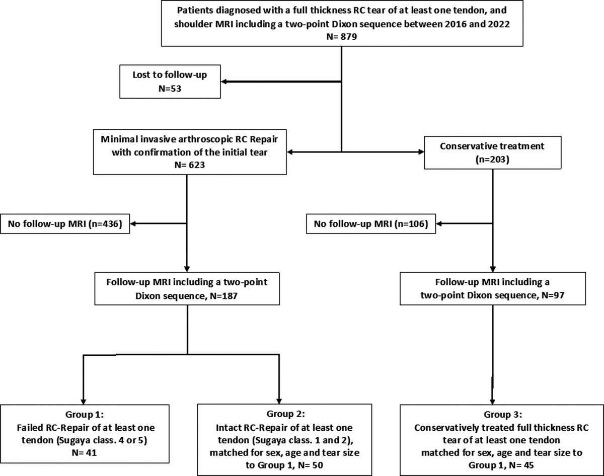
MATERIALS AND METHODS PatientsBetween February 2021 and November 2021, 3118 patients underwent clinically indicated CT scans of the chest and/or abdomen and pelvis during office hours, with and without intravenous contrast media. A 128-slice single-source CT scanner (SOMATOM x.cite; Siemens Healthineers, Forchheim, Germany) was used. The study was registered in clinicaltrials.gov (ID: NCT05135208). Institutional review board approval was obtained (SZ_W_106.20-RD). Written informed consent was waived.
Patients from one group were positioned laser-guided by highly trained technicians with a mean experience of 12.5 years (5–30 years) (camera off), and patients from the other group were positioned guided by the 3D camera (camera on) under the surveillance of technicians. In the latter group, the technicians were instructed to interfere only in cases of severe deviation, as indicated by the optical laser.
Exclusion criteria were patients' age younger than 18 years, body mass index (BMI) over 55 m/kg2, and patients from the intensive care units, often being monitored with multiple life support devices, that can potentially affect surface recognition.
Dose Management SystemA dose management system (DMS; Radimetrics; Bayer Vital GmbH, Leverkusen, Germany) was used to record the following parameters: CT dose index (CTDIvol), dose length product (DLP) and organ doses of the heart, eye lenses, colon, ovaries, red bone marrow, thyroid, salivary glands, esophagus and ED with applied different tissue weighting factors as recommended by the International Commission on Radiological Protection (ICRP 103).
Isocenter accuracy and table height, patient's height and weight, age, sex, BMI, and reconstruction diameter were extracted from DICOM (Digital Imaging and Communications in Medicine) information.
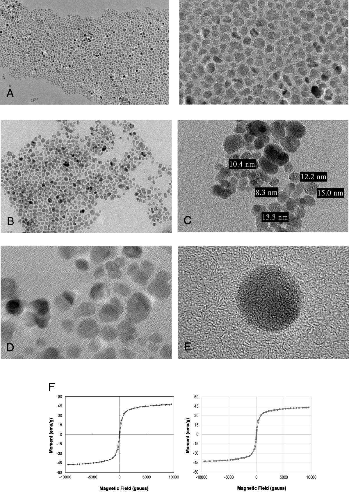
Only diagnostic series were extracted using DMS. The DMS also provided table height and object isocenter (Fig. 1). Details of the DMS have been reported previously.27 To verify these parameters, additional measurements with a male anthropomorphic Alderson-Rando phantom (Radiology Support Device, Long Beach, CA) were performed.
 FIGURE 1:
 Sagittal multiplanar reconstruction of a patient with the extracted isocenter line along the z axis with applied dose modulation line.
Subject isocenter as defined by DMS is the mean of the patient's diameter of each slice over the scan range.
The camera system (Kinect V2; Microsoft, Redmond, WA) was positioned on the ceiling above the CT table to capture the complete patient with an optical, an infrared and a motion sensor.25 For each individual pixel, the time for the light to reach the surface of the object and back to the camera (time-of flight technique) is measured, creating a 3D point cloud. This “depth image” serves as the basis for the algorithm to calculate the center-line of the patient.25 To avoid sources of inaccuracies that could cause an increased noise in the surface data, patients were examined without blankets, bathrobes, or loose-fitting outerwear.
Statistical AnalysisA sample size of 1806 patients for each group was calculated (G*Power; HHU, Düsseldorf, Germany28) to detect an effective size of 0.12 for radiation exposure analysis. Five test measurements with an anthropomorphic phantom were performed, starting at the isocenter (0 cm) with an increment of 2 cm and a table height shift from −4 cm to +4 cm with same scan protocols. Dose length product and CTDIvol was extracted from DICOM data on each phantom scan at the level of the carina.
For the sample size analysis regarding isocenter accuracy, a group size of 10 patients in each group according to previous results8 were calculated (G*Power; HHU, Düsseldorf, Germany28) to detect an effective size of 1.72 for chest CT and 1.77 for abdominal CT. All statistical tests were performed using commercially available software (SPSS version 25.0; SPSS, Chicago, IL). A χ2 test was used to analyze patients' characteristics.
Levine test was used for calculating the equality of variances followed by Student t test for independent samples. A P value <0.05 was considered indicating statistically significant differences.
RESULTSAll examinations were performed without complications. Patient characteristics such as body weight, size, BMI, age, and sex and acquisition parameters were similar in the 2 groups (Table 1). In the study cohort composed of 1321 examinations of the chest (681 with and 640 without 3D camera), 951 examinations of the chest and abdomen (390 with and 419 without 3D camera), and 809 examinations of the abdomen (407 with and 439 without 3D camera), 205 patients were excluded because of camera malfunction after software update. All examinations of the abdomen also included the pelvis.
TABLE 1 - Patient Characteristics and the Applied Exposure Factors Camera Mode N Mean Value Standard Deviation P Isocenter, mm Off 1557 −10.9 16.6 0.000 On 1561 −3.8 10.1 Reconstruction diameter, mm Off 1557 400.8 40.8 0.251 On 1561 399.2 40.1 Pitch Off 1557 0.8 0.2 0.894 On 1561 0.8 0.2 mAS max Off 1557 219.8 114.2 0.042 On 1561 211.2 112.2 kVp Off 1557 94.8 18.6 0.796 On 1561 95.0 18.8 Table height, mm Off 1557 170.0 20.4 0.000 On 1561 165.6 16.2 Age, y Off 1557 64.1 15.8 0.423 On 1561 63.7 16.1 BMI, kg/m2 Off 1557 26.1 5.4 0.957 On 1561 26.1 5.5 Weight, kg Off 1557 76.2 18.4 0.885 On 1561 76.3 18.0 Height, mm Off 1557 1704.6 97.8 0.506 On 1561 1707.0 96.4mAs, milliampere seconds; kVp, kilovoltage peak; BMI, body mass index.
Accuracy of isocenter positioning between the 2 groups differed significantly (P < 0.001); the mean deviation between scanner isocenter and patient isocenter was 3.8 mm (SD = 10.1 mm) with and 10.9 mm (SD = 16.6 mm) without use of the camera.
The mean table height from isocenter toward x-ray tube was 165.6 mm (SD, 16.2 mm) when positioned with and 170.0 mm (SD, 20.4 mm) when positioned without the use of the 3D camera (P < 0.001).
Differences in patient positioning should affect AEC and ATVS and therefore have an impact on radiation exposure of the patients: the mean DLP in the patient cohort scanned with camera-based positioning was 321.1 mGy·cm (SD, 266.6 mGy·cm), mean CTDIvol = 6.4 mGy (SD, 4.3 mGy), the respective mean values in the control group were DLP = 342.0 mGy·cm (SD, 280.7 mGy·cm) and CTDIvol = 6.8 mGy (SD, 4.6 mGy). Both groups differed significantly (P = 0.033, and P = 0.011) (Fig. 2). The mean ED was 3.3 mSv (SD, 2.7 mSv) in the camera and 3.5 mSv (SD, 2.9 mSv) in the group with manual positioning (P = 0.053).
 FIGURE 2:
 Scatterplot illustrating the data relationship between the deviation from patient's isocenter (in millimeter) and the patient's radiation exposure (CTDIvol in milligray) when the camera was switched on and off.
Exposure of radiation-sensitive organs such as colon (P = 0.015) and red bone marrow (P = 0.049) was also lower using the camera (Table 2).
TABLE 2 - Dose Length Product in mGy·cm, Effective Dose in mSv, CT Dose Index in mGy, and Organ Dose in mSv Camera Mode N Mean Value Standard Deviation P ED Off 1557 3.5 2.9 0.053 On 1561 3.3 2.7 DLP Off 1557 342.0 280.7 0.033 On 1561 321.1 266.7 CTDIvol Off 1557 6.8 4.6 0.011 On 1561 6.4 4.3 Organ dose of eye lens Off 1557 0.1 0.1 0.21 On 1561 0.1 0.3 Organ dose of heart Off 1557 3.9 3.1 0.443 On 1561 3.8 3.0 Organ dose of colon Off 1557 3.5 3.9 0.015 On 1561 3.1 3.6 Organ dose of ovaries Off 1557 3.1 3.6 0.902 On 1561 3.1 3.5 Organ dose of red bone marrow Off 1557 2.4 2.1 0.049 On 1561 2.3 1.9 Organ dose of thyroid gland Off 1557 0.3 0.4 0.205 On 1561 0.3 0.8 Organ dose of upper colon Off 1557 3.7 3.9 0.012 On 1561 3.3 3.6 Organ dose of salivary glands Off 1557 0.0 0.0 0.226 On 1561 0.0 0.2 Organ dose of esophagus Off 1557 2.3 1.7 0.355 On 1561 2.2 1.7DLP, dose length product; ED, effective dose; CTDIvol, CT dose index.
For patients with BMI <25 kg/m2, the results were as follows: isocenter accuracy was 4.1 mm (SD, 9.7 mm) with camera on and 12.8 mm (SD, 14.8 mm) camera off (P < 0.001), CTDIvol = 4.7 mGy (SD, 2.48 mGy) and 4.92 mGy (SD, 2.78 mGy) (P = 0.094), DLP = 232.57 mGy·cm (SD, 160.21 mGy·cm) and 244.48 mGy·cm (SD, 174.26 mGy·cm) (P = 0.166). Radiation exposure of the colon was significantly different (P = 0.043), but not for red bone marrow (P = 0.143).
For patients with BMI >25 kg/m2, the results were as follows: isocenter accuracy was 3.5 mm (SD, 10.4 mm) with camera on and 9.2 mm (SD, 18.0 mm) camera off (P < 0.001), CTDIvol = 8.6 mGy (SD, 5.3 mGy) and 8.1 mGy (SD, 4.9 mGy) (P = 0.05), DLP = 432.0 mGy·cm (SD, 326.3 mGy·cm) and 406.5 mGy·cm (SD, 316.4 mGy·cm) (P = 0.112). Radiation exposure of the colon (P = 0.105) and red bone marrow (P = 0.162) differed not significantly.
All patients positioned with the camera were within a range of ±4 cm from the patient isocenter. Only 25 patients were positioned 2–4 cm above and 72 patients 2–4 cm below the isocenter. The other patients were positioned within a range of ±2 cm from the isocenter, 465 above and 999 below the isocenter.
Seventy-two patients positioned without the camera were outside the range of ±4 cm from the patient isocenter, 4 patients above and 68 patients below the isocenter. Thirty-seven patients were positioned 2–4 cm above and 376 patients 2–4 cm below the isocenter. The other patients were positioned within a range of ±2 cm from the isocenter, 340 above and 732 below the isocenter.
Tube voltage selection was 70–80 kV in 520 and 500 patients (camera on/camera off), 90 kV in 642 and 681 patients, 100–110 kV in 188 and 113 patients, 120–150 kV in 284 and 266 patients.
DISCUSSIONDose awareness has become a major topic in the last years, and a range of different measures have been produced with the aim to reduce patient exposure. Automatic exposure control, iterative and artificial intelligence–based reconstruction techniques, ATVS, and tube current modulation are powerful tools to accomplish this task. Although advanced reconstruction techniques are independent of isocenter scanning, tube current modulation/AEC and ATVS depend on accurate patient positioning to tap the full potential. These techniques heavily rely on the attenuation and the size of the subject in the scout view/topogram. Automatic exposure control algorithms face the problem to modelize a 3D object (patient) from a 2D scout view. In thoracoabdominal CT, the scout view is usually performed in posterior-anterior view. Dose calculation in the posterior-anterior direction is quite accurate, because attenuation is directly measured. Dose calculations for the lateral projections are made from estimations of the patient size derived from the body contours of the posterior-anterior scout view if no additional lateral scout view is acquired. Vertical off-center positioning may therefore result in suboptimal assumptions. If the patient's position deviates toward the x-ray tube, geometric distortion on the scout view of body contours will simulate a larger patient, which would trigger higher tube current demand. In contrary, if the patient is positioned too near toward the detector, a lower tube current demand will be assumed (Supplement 1, https://links.lww.com/RLI/A737). Off-centering also influences ATVS, albeit indirectly. Calculations of the optimal kV-setting are premised on the tube current estimates of the AEC algorithm, which uses the tube-output capacity at different levels of tube voltage over the scan range and the forecasted radiation exposure at different kV levels to select the appropriate scan setting. The better the predictions of the tube current demand, the more exact the kV selection will be. Once the tube voltage is selected, there is no further adjustment during the scan to correct for suboptimal prior assumptions. This supports the additional expenses to further improve exact isocenter positioning. Laser lines projected on the patient help to adjust the table height properly; this tool is included in all clinical scanners, but visual positioning still is user dependent, and even for experienced technicians, it is not always trivial. A highly sophisticated solution is the use of a 3D camera, which uses surface and depth information to adjust the table height. It has been reported that this technique reduces the mean deviation from the optimal position and especially the variation in patient off-set.8
Camera-based patient positioning was feasible in all patients, and manual intervention was not necessary. The overall deviation from the isocenter was small in both groups, 10.1 mm for the camera-based positioning and 16.6 mm for manual positioning. Although only technicians with a very high training level in CT participated in this study, patient positioning in the camera-based group was more precise. The absolute deviation from isocenter as well as the lower standard deviation with the camera suggest a more reliable approach, which is the basis for consistent dose and image quality optimization.
Negative effects of off-center scanning has been reported previously7,29; 2 cm deviation from the isocenter had a significant impact on specific radiation-sensitive organs (up to 38% in the thyroid). On the other hand, effect on overall image quality and radiation exposure was rather low, if off-centering was below 2 cm.30 We had a relevant number (n = 485) of patients with a deviation of more than 2 cm from isocenter in the manual positioning group, despite the high training level of the technicians. We assume that the effect of deviation from isocenter might be higher in technicians who do not have such experience in performing CT examinations. In the camera group, this off-center rate was significantly lower (n = 97, χ2 = 0.000).
Deviation of 4 cm results in an increase in dose up to 20% according to Monte Carlo simulations in an anthropomorphic chest phantom.30 The camera-based algorithm prevented such a dimension of off-centering completely, in manual positioning off-centering of 4 cm, and more was found in 72 patients.
As indicated by Saltybaeva et al8 that optimal table height does not necessarily result in lower radiation exposure in the individual patient as compared with visual positioning. If a technician consistently positions the patient for the scout view off-center, in a position toward the detector, patient exposure will be lower, but image quality might be degraded by higher image noise. Figure 2 shows that more patients were positioned in a lower than optimal position, which increases radiation exposure and may prevent using a low-kV protocol in some cases. Most of our patients were scanned with a low-kV protocol (70–90 kV), although without significant difference between both groups.
The impact of optimal patient positioning on patient exposure was statistically significant with a mean difference between the 2 groups in table height of 4.4 mm and a mean difference in isocenter accuracy of 7.1 mm, which led to an increase of 5.1% in DLP, 5.8% in ED, and 6.2% in CTDIvol when positioned manually.
LimitationsWe did not evaluate the image quality, because we had no reference standard available. Our focus was on chest and abdomen examinations; these results cannot be transferred to head and neck examinations. Although positioning of the head can be achieved quite well focusing the laser cross on the auditory canal, this might be different for neck examinations. Further studies are necessary for these regions.
ConclusionsImplementation of a 3D camera improves and homogenizes patient positioning for common CT examinations (chest, abdomen, and pelvis). Although most of our patients were positioned within a range of ±4 cm by experienced technicians, the camera-based algorithm positioned all patients within that range with a much lower standard deviation. Correct positioning in the isocenter improves the accuracy of AEC and ATVS and also resulted in lower radiation exposure, independently from the BMI.
Only experienced and highly trained technicians participated at our study; the benefit of a camera system may be even greater when less experienced staff is involved.
REFERENCES 1. Schegerer A, Loose R, Heuser LJ, et al. Diagnostic reference levels for diagnostic and interventional x-ray procedures in Germany: update and handling. Rofo. 2019;191:739–751. 2. Cool DA, Kase KR, Boice JD. NCRP report no.180-management of exposure to ionizing radiation: NCRP radiation protection guidance for the United States. J Radiol Prot. 2019;39:966–977. 3. Ria F, Davis JT, Solomon JB, et al. Expanding the concept of diagnostic reference levels to noise and dose reference levels in CT. AJR Am J Roentgenol. 2019;213:889–894. 4. European Commission, Directorate-General for Energy. Medical radiation exposure of the European population. Publications Office; 2015. Available at: https://data.europa.eu/doi/10.2833/708119. Accessed February 13, 2022. 5. Schegerer AA, Nagel HD, Stamm G, et al. Current CT practice in Germany: results and implications of a nationwide survey. Eur J Radiol. 2017;90:114–128. 6. Tsapaki V, Damilakis J, Paulo G, et al. CT diagnostic reference levels based on clinical indications: results of a large-scale European survey. Eur Radiol. 2021;31:4459–4469. 7. Kaasalainen T, Palmu K, Reijonen V, et al. Effect of patient centering on patient dose and image noise in chest CT. AJR Am J Roentgenol. 2014;203:123–130. 8. Saltybaeva N, Schmidt B, Wimmer A, et al. Precise and automatic patient positioning in computed tomography: avatar modeling of the patient surface using a 3-dimensional camera. Invest Radiol. 2018;53:641–646. 9. van Straten M, Deak P, Shrimpton PC, et al. The effect of angular and longitudinal tube current modulations on the estimation of organ and effective doses in x-ray computed tomography. Med Phys. 2009;36:4881–4889. 10. Mulkens TH, Bellinck P, Baeyaert M, et al. Use of an automatic exposure control mechanism for dose optimization in multi-detector row CT examinations: clinical evaluation. Radiology. 2005;237:213–223. 11. Kalra MK, Maher MM, Toth TL, et al. Techniques and applications of automatic tube current modulation for CT. Radiology. 2004;233:649–657. 12. Barreto I, Lamoureux R, Olguin C, et al. Impact of patient centering in CT on organ dose and the effect of using a positioning compensation system: evidence from OSLD measurements in postmortem subjects. J Appl Clin Med Phys. 2019;20:141–151. 13. Lell MM, Kachelrieß M. Recent and upcoming technological developments in computed tomography: high speed, low dose, deep learning, multienergy. Invest Radiol. 2020;55:8–19. 14. Lell MM, Wildberger JE, Alkadhi H, et al. Evolution in computed tomography: the battle for speed and dose. Invest Radiol. 2015;50:629–644. 15. Lurz M, Lell MM, Wuest W, et al. Automated tube voltage selection in thoracoabdominal computed tomography at high pitch using a third-generation dual-source scanner: image quality and radiation dose performance. Invest Radiol. 2015;50:352–360. 16. Ketelsen D, Buchgeister M, Fenchel M, et al. Automated computed tomography dose-saving algorithm to protect radiosensitive tissues: estimation of radiation exposure and image quality considerations. Invest Radiol. 2012;47:148–152. 17. Damilakis J. CT dosimetry: what has been achieved and what remains to be done. Invest Radiol. 2021;56:62–68. 18. Runge VM, Marquez H, Andreisek G, et al. Recent technological advances in computed tomography and the clinical impact therein. Invest Radiol. 2015;50:119–127. 19. Lell M, Wucherer M, Kachelrieß M. Dosis und Dosisreduktion in der Computertomografie. Radiologie Up2date. 2017;17:163–178. 20. Kaasalainen T, Palmu K, Lampinen A, et al. Effect of vertical positioning on organ dose, image noise and contrast in pediatric chest CT—phantom study. Pediatr Radiol. 2013;43:673–684. 21. Toth T, Ge Z, Daly MP. The influence of patient centering on CT dose and image noise. Med Phys. 2007;34:3093–3101. 22. Gudjonsdottir J, Svensson JR, Campling S, et al. Efficient use of automatic exposure control systems in computed tomography requires correct patient positioning. Acta Radiol. 2009;50:1035–1041. 23. Habibzadeh MA, Ay MR, Asl AR, et al. Impact of miscentering on patient dose and image noise in x-ray CT imaging: phantom and clinical studies. Phys Med. 2012;28:191–199. 24. Matsubara K, Koshida K, Ichikawa K, et al. Misoperation of CT automatic tube current modulation systems with inappropriate patient centering: phantom studies. AJR Am J Roentgenol. 2009;192:862–865. 25. Booij R, Budde RPJ, Dijkshoorn ML, et al. Accuracy of automated patient positioning in CT using a 3D camera for body contour detection. Eur Radiol. 2019;29:2079–2088. 26. Dane B, O'Donnell T, Liu S, et al. Radiation dose reduction, improved isocenter accuracy and CT scan time savings with automatic patient positioning by a 3D camera. Eur J Radiol. 2021;136:109537. 27. Smith-Bindman R, Moghadassi M, Wilson N, et al. Radiation doses in consecutive CT examinations from five University of California Medical Centers. Radiology. 2015;277:134–141. 28. Faul F, Erdfelder E, Lang A-G, et al. G*power 3: a flexible statistical power analysis program for the social, behavioral, and biomedical sciences. Behav Res Methods. 2007;39:175–191. 29. Filev PD, Mittal PK, Tang X, et al. Increased computed tomography dose due to miscentering with use of automated tube voltage selection: phantom and patient study. Curr Probl Diagn Radiol. 2016;45:265–270. 30. Saltybaeva N, Alkadhi H. Vertical off-centering affects organ dose in chest CT: evidence from Monte Carlo simulations in anthropomorphic phantoms. Med Phys. 2017;44:5697–5704.
留言 (0)