
記住我

Tibial fractures are common in traumatology orthopedics with an incidence of two per 10,000 population1, most of which are high-energy injuries and always accompanied by significant soft tissue injuries2. There is a lack of a consensus on the management of distal tibial fractures, since surgical treatment needs to ensure a stable fixation while minimizing secondary injury to soft tissue induced by the surgical approach and implants3, 4.
Excellent fracture reduction and the proper choice of a fixation device may provide better clinical outcomes. For metaphyseal fractures or those at the metaphyseal-diaphyseal junction, the fixation device chosen and technique is controversial. Conventional external fixation and internal fixation with plates are still considered effective fixation methods when managing tibial fractures currently. However, reports have shown more complications in soft tissues, including pin tract infections5, superficial or deep infections, delayed wound healing, and necrosis of soft tissues due to the unique blood supply and anatomical characteristics6-9, resulting in an increased application of intramedullary nail fixation, which obtains an extra benefit of being a load sharing device to allow early weight bearing6, 10, 11.
Since tibial intramedullary nail fixation has little interference with the soft tissue surrounding the fracture site and shows a high rate for fracture union, it has become the standard treatment of choice for displaced tibial fractures in adults12-14. Previous studies7, 8, 15 noted that intramedullary nails have shorter operative time in the treatment of tibial fractures and better postoperative function recovery. However, some deficiencies of intramedullary nailing fixation still exist, such as anterior knee pain, which proved to be one frequently discussed and cited complication, researchers reported16 an incidence of 56.2%, manifested worse in younger patients and frequently required the nail to be removed. Another issue with nailing is malalignment17, including primary malalignment that is originated intraoperatively due to an imperfect reduction, and secondary malalignment that develops postoperatively due to the instability of the bone-implant construct18. Some authors have reported a high incidence of malalignment in tibial fractures treated using an intramedullary nail19, 20. Therefore, prevention of secondary malalignment is mainly dependent on biomechanical features of the intramedullary nailing and the implant to bone interface, whereas, prevention of the primary malalignment, the common coronal plane varus/valgus angulation of the fracture zone intraoperatively remains a challenge when treating these injuries. This is especially due to the inability to directly view the fractured site and film the entire tibia with intraoperative C-arm fluoroscopy when performing closed reduction and tibial intramedullary nail fixation. It is a huge challenge to determine whether the distal tibia valgus or varus angulations occur in the fracture zone during the surgery due to the medullary canal widening and filling with weaker cancellous bone at the distal tibia21. It has also been reported that even a small amount of residual alters load through the knee and ankle joint17, and the alternation in force may attribute a predisposition to osteoarthritis22, 23. Despite poor early results using intramedullary nailing of tibia fractures, improvements in surgical techniques and implant design modifications have resulted in more satisfactory outcomes.
The authors sought to identify an easy, applicable and reproducible method that can be applied using conventional tools during surgery to determine coronal plane deformities of the distal tibia in the treatment of tibial fractures with intramedullary nail fixation. The correlation between the direction of the distal blocking screw and tibiotalar joint representing the coronal plane angulation of the distal tibial fragment in the fracture zone were considered as an intuitive and effective method. It is necessary for the surgeons to intraoperatively recognize and correct coronal plane varus/valgus angulation of the fracture zone, neutralize the forces and restore a satisfactory reduction.
In this study, this study retrospectively analyzed data collected from 33 patients with comminuted tibial fractures treated with tibial intramedullary nails from January 2018 to January 2019. This study used the parallel relationship between the distal horizontal interlocking screw and the tibiotalar joint surface on anteroposterior fluoroscopy films to determine the onset of valgus or varus angulation of the distal tibial fragment. The purpose of this study was as follows: (i) aiming to expound the fundamental causes and prevention methods of valgus or varus deformity during the intramedullary nailing surgery for the treatment of tibial fracture; (ii) aiming to provide another intuitive perspective for intraoperatively determining and avoiding coronal plane deformities of the distal tibia in the treatment of tibial fractures using intramedullary nail fixation; and (iii) aiming to confirm the feasibility and significance for developing the approach to intraoperatively identify the coronal plane deformities by analyzing the lateral distal tibial angle and clinical outcomes of the unaffected and affected sides.
Material and Methods Inclusion and Exclusion CriteriaInclusion criteria: (i) patients over 18 years of age; (ii) AO/OTA classification: type 42-B3 and type C tibia fracture; and (iii) no existing deformities of the knee, ankle joints or tibia present before the injury. Exclusion criteria: (i) Gustilo–Anderson type III open tibia fracture; (ii) preoperative deformities around the knee or ankle joint before the injury; (iii) the presence of a simple tibia fracture, 42-A, B1 and B2 types according to AO/OTA classification; (iv) the onset of serious knee and ankle joint diseases, such as rheumatoid arthritis and gouty arthritis; and (v) patients who refused surgery.
Research DesignA single-center, retrospective study was conducted at our trauma center from January 2018 to January 2019. All eligible data were collected and reviewed based on the clinical material database including age, gender, mechanism of injury, AO/OTA classification and Gustilo–Anderson classification24, the average interval from injury to surgery, the lateral distal tibial angle (LDTA) of the unaffected and affected sides, complications and the Olerud–Molander ankle score.
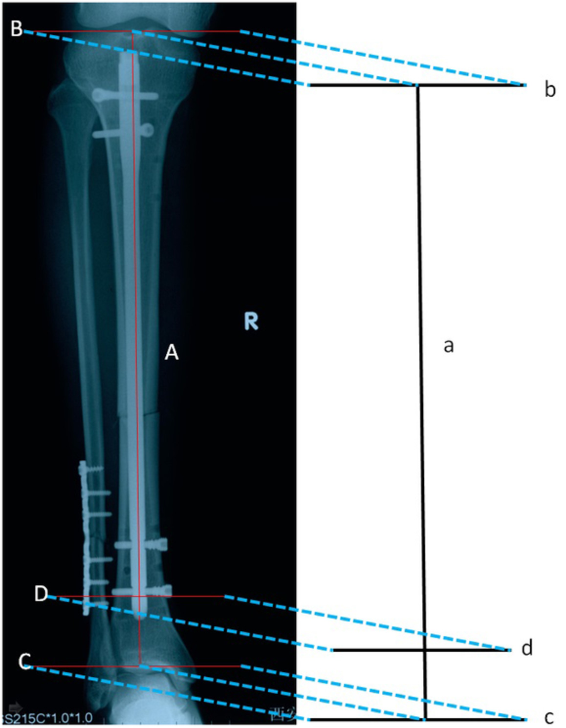
Approach Determining the Onset of Valgus or Varus Deformities of the Distal TibialC-arm fluoroscopy films were used to obtain standard anteroposterior views. The tibial intramedullary nail was projected as a vertical line (line a, Fig. 1) on the coronal plane. Therefore, when the intramedullary nail was inserted through the standard entry point, line a would be perpendicular to the projection line of the knee joint surface (line b) on the coronal plane. Theoretically, when the distal tibia does not combine with the concomitant valgus or varus deformities, line a would also be perpendicular to the projection line of the tibiotalar joint plane (line c) on the coronal plane. Meanwhile, the projection line of the distal horizontal interlocking screw axis (line d) on the coronal plane is designed to be perpendicular to intramedullary nail (line a). Based on the geometrical theory that if a straight line is vertically intersected by multiple straight lines in the same plane, then these intersected lines must be parallel with one another. Theoretically, the three lines of the knee joint plane, the distal horizontal interlocking screw and the tibiotalar joint surface projected on the coronal plane should be parallel (lines b, c and d are parallel to one another and are simultaneously perpendicular to the line a). Moreover, the distal interlocking screw and the tibial intramedullary nail were both composed of metal materials25, thus there is a low probability for generating a deviation in the locking process (line d and line a were designed to be perpendicular to each other). Therefore, if an included angle emerged between the projection lines of the distal horizontal interlocking screw and the tibiotalar joint plane on the coronal plane (line d and line c are not parallel to each other) (see Fig. 3), it is demonstrated that the valgus or varus deformities occur at the fracture of the distal tibia in the coronal plane. Meanwhile, the fibula can be used as a reference. If the included angle points to the fibular side, the valgus deformity occurs, and if the angle faces away from the fibula, then varus deformity occurs.

General view of the projection line on the coronal plane. The tibial intramedullary nail projection line (line a), the knee joint surface projection line (line b), the tibiotalar joint surface projection line (line c) and the axis of distal horizontal interlocking screw projection line (line d).
Surgical ProcedureBefore the operation, the anteroposterior and lateral views of the entire tibia were performed to determine the severity degree, location and displacement of the fracture fragments. CT scans were conducted to identify the fracture of joint in patients who had fracture lines affect the knee or ankle joint surface. Patient received epidural or general anesthesia in the supine position on a radiolucent orthopedic surgical table. The tourniquet was placed to the proximal thigh after anesthesia, and the hip on the affected side was raised. Open fractures were irrigated and debrided. The lateral malleolus was fixed using a lateral approach with plates in respect to fibula fractures and fracture line located within 8 cm above the ankle mortise.
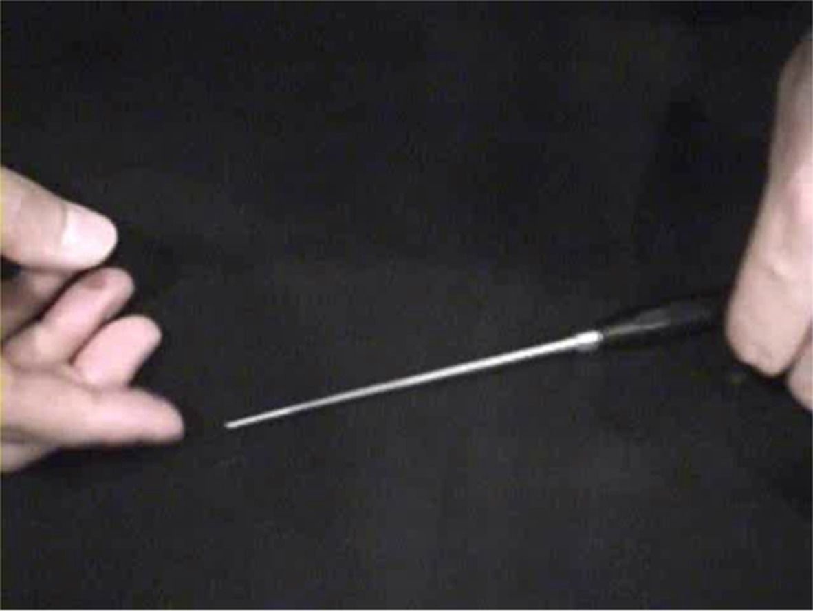
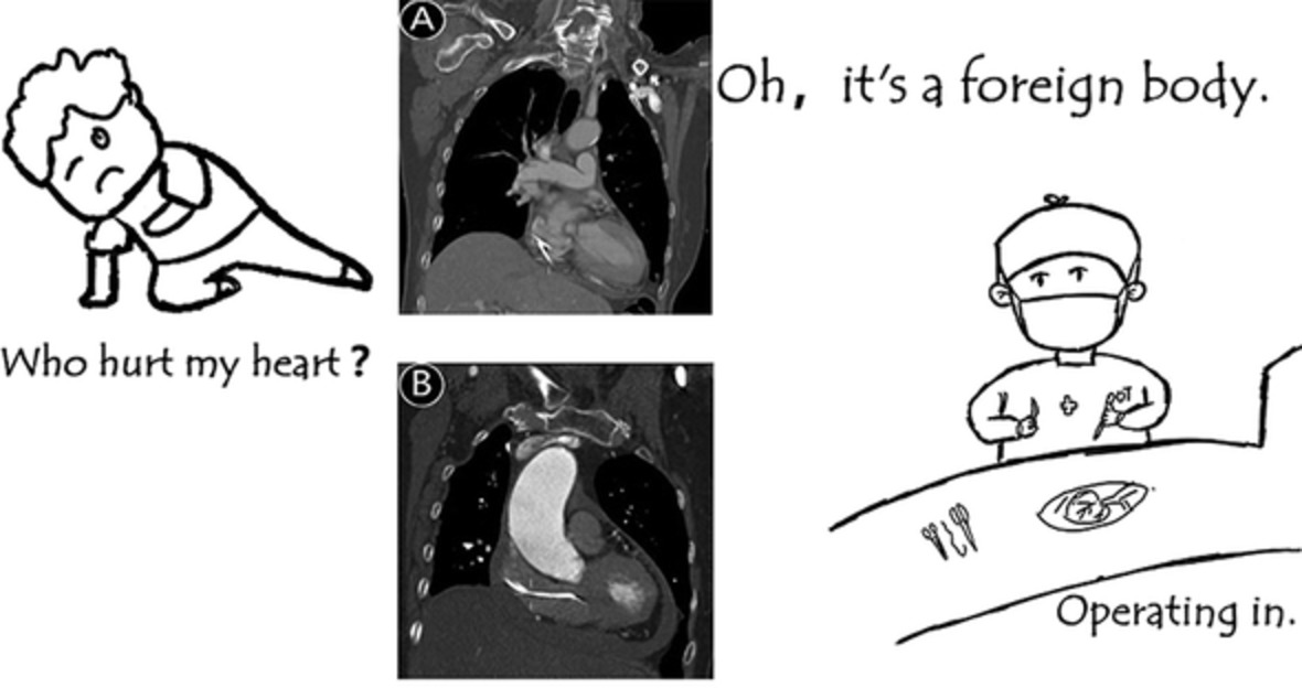
Then, the classical nailing procedure was performed. A standard anterior patellar approach was adopted by splitting the patellar tendon to expose the tibial plateau slope. The ideal entry point should be just medial to the lateral tibia spine on the AP fluoroscopic view and just anterior to the articular surface on the lateral view26 (Fig. 2). After preparation of the entry portal by awl with the knee hyperflexed, longitudinal traction and appropriately directed forces were manually applied to the limb to obtain provisional alignment and fulfill fracture reduction. Fracture reduction was maintained by a surgical assistant and the appropriate length and diameter of an intramedullary nail was inserted along the guide wire after gradual reaming. Locking bolts were placed and locked with the nail at proximal and distal holes. C arm fluoroscopic images were used to confirm if an included angle occurred between the axis of the distal horizontal interlocking screw and the horizontal line of the tibiotalar articular surface on the AP film. If necessary, the poller screw technique was performed to correct angulation deformities (Fig. 3). Finally, the tail cap was installed. Once a satisfactory reduction was achieved on fluoroscopy, irrigation and suction drainage were performed and then the incision was closed sequentially(Fig. 4).

A schematic of the ideal starting point of intramedullary nailing. (A) The ideal starting point of the guide wire on the AP views intraoperatively. (B) The ideal starting point of the guide wire on the lateral views intraoperatively.

A representative case where a 21-year-old male who experienced a road traffic accident that resulted in left calf and right knee pain with limited activity. Radiograph at the emergency room demonstrated left tibia and fibula fractures combined with contralateral tibial plateau fractures. (A) Left tibia and fibula fractures (AO/OTA 42-C3) as shown by the AP views. (B) Left tibia and fibula fractures (42-C3) on the lateral views. (C) The insertion of the finger reduction device through a guide wire. (D) The insertion of the nail after gradual reaming and the distal interlocking screws were locked by the free hand procedure. An included angle emerged between line c and line d, which pointed to the fibula on the hand drawing diagram of intraoperative image intensification. (E) The AP view of the distal fragment demonstrated a valgus deformity. (F) Reinsertion of the nail after application of the poller screw technique for the distal tibial fragment. (G) The parallel relationship between line c and line don image intensification and the hand drawing diagram indicated the correction of the valgus deformity intraoperatively.

Postoperative radiographic results demonstrated satisfactory reduction, alignment and implant location. (A) The AP view of X-ray films 2 days after surgery. (B) The lateral view of X-ray films 2 days after surgery.
Postoperative ManagementThe affected limb raised, and routine second-generation cephalosporin antibiotics were applied for 24 h after surgery to prevent infection. Two days after the operation, postoperative X-rays were taken and patients were encouraged to partake in active and passive functional exercises to help the affected knee, ankle, and toes. CPM machine-assisted exercises were performed if necessary. Thrombolytics or anticoagulant therapies were given to patients after surgery to prevent deep vein thrombosis of the lower extremities.
Bilateral full-length anteroposterior and lateral X-rays were performed for the lower limbs after removing the drainage tube in order to investigate the reduction and implant location, and to measure the LDTA on both affected and contralateral sides. Thus, showing whether the distal tibia showed valgus or varus deformities could be determined.
The LDTA was used to estimate existing deformities in the coronal plane of the fracture according to Paley's deformity analysis method27. Follow-up visits took place once a month for the first 3 months after surgery and were then extended to every 3 to 6 months after the first 3 follow-ups, and finally to every 6 to 12 months a total of 1 year after surgery.
Outcome MeasuresOutcome indicators included the LDTA of the unaffected and affected sides, the complication rate and the Olerud–Molander ankle score.
Lateral Distal Tibial Angle (LDTA)LDTA is the lateral angle formed between the mechanical axis line of the tibia and the ankle joint line of the tibia in the frontal plane, it is commonly accepted to use the line perpendicular to the tibial diaphysis as the joint orientation line for the ankle. The normal range of LDTA is 89° ± 3°. Distal tibia valgus deformities are considered to be present when LDTA was lower than 86 degrees and the varus deformity for LDTA was greater than 92 degrees. According to the current most commonly accepted reduction criteria, a varus or valgus angulation deformity over 5 degrees required reoperation28, 29.
Olerud–Molander Ankle Score (OMAS)The OMA score is a validated, condition specific and patient reported measure describing outcomes in nine domains: pain (0 to 25), stiffness (0 to 10), swelling (0 to 10), stair climbing (0 to 10), running (0 to 5), jumping (0 to 5), squatting (0 to 5), mobility supports and work (0 to 10), activities of daily life (0 to 20). The score standard had a maximum of 100 points (higher scores indicating better outcomes and fewer symptoms).
Statistical AnalysisStatistical analysis was performed using the SPSS 24.0 statistical software (IBM, Armonk, NY, USA). A Shapiro–Wilk test for normality was conducted for all continuous data, and continuous data with normal distributions were described in the form of mean ± standard deviation. Whereas categorical data were described in number of cases (percentages). Continuous data with normal distributions, such as the LDTA between the affected and contralateral unaffected sides were analyzed by Student's t-test and the Mann–Whitney U-test for those not with the normal distribution. As for the categorical variables, the χ2 test was performed. P < 0.05 was selected as the threshold for statistically significant.
Results Demographic Data and Follow-UpsA total of 33 consecutive patients who were postoperatively followed up for 13 to 25 months (mean 18.7 months) were enrolled in this study. Out of these patients, 23 were male and 10 were female with an average age of 41 years (ranging 22 to 69 years of age). In relation to mechanism of injury, 26 cases resulted from road traffic accidents and seven cases were a result of accidental falls. Based on the AO/OTA classification, there were seven cases of type B3, four cases of C1, 10 cases of C2 and 12 cases of C3. Of the five open fractures, there were three Gustilo type I and two type II cases. The average interval from injury to surgery was 4.3 days (2 to 11 days).Fractures achieved bone union at an average of 4.3 months (ranging from 3 to 6 months). The LDTA the unaffected side measured postoperatively was 87.3° to 89.6° (average 88.7° ± 0.8°), and the LDTA of the affected side was 87.5° to 90.4°(average 88.9° ± 1.1°). There was no significant difference observed between the unaffected and the affected sides (t = −1.865, P = 0.068).
Intraoperative Radiographic ImprovementThere were 24 normal cases, six cases showing valgus angulations and three cases showing varus angulations. All valgus or varus deformities were corrected during surgery.
Complications and Clinical ImprovementsThe total complication rate observed in this study was 60.6% (20 cases), including four cases that showed deep vein thrombosis and then received anticoagulant therapy, one case of infection and delayed union that was treated with surgical debridement and autologous bone graft. Fifteen cases of slight to moderate anterior knee pain were also noticed, which may be one of the most frequently discussed complications at the last follow up visits; these patients were advised to received multimodal analgesia therapy. According to the Olerud–Molander ankle score30, clinical outcomes indicated 22 excellent, eight good, two normal and one poor case 12 months after surgery. The rate of excellent and good cases was 90.9%(Fig. 5). There was one case with poor efficacy belonging to AO/OTA type C3 and Gustilo–Anderson II open fracture. Tibial intramedullary nail fixation was performed 1 week after debridement and external fixation. Infection occurred in this patient 5 days after nailing fixation. The debridement procedure was repeated and the internal fixation method was replaced by external fixation. The ankle joint function of this patient showed poor outcomes after infection control at late stage.

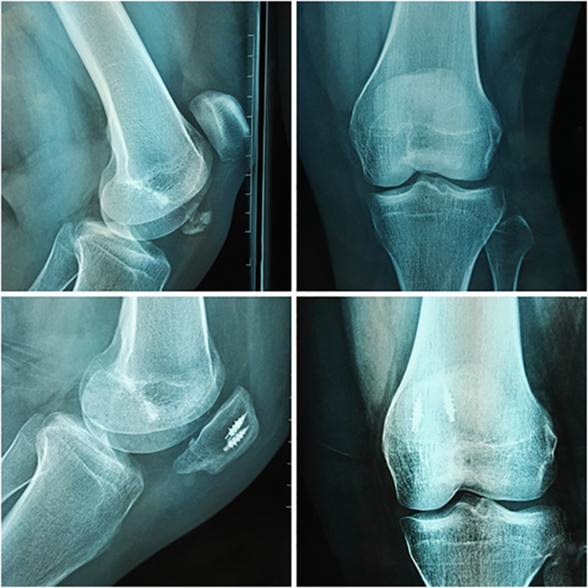
Functional outcomes 1 year after surgery. (A) The plantarflextion of the ankle joint at 1 year follow-up. (B) The dorsiflexion of the ankle joint at 1 year follow-up. (C) Range of motion for the knee joint at 1 year follow-up. (D) The AP view of the postoperative radiograph at 1 year follow-up. (E) The lateral view of the postoperative radiograph at 1 year follow-up.
DiscussionCurrently, intramedullary nailing is the most valid and popular fixation option used for tibial fractures despite many other surgical treatment options12, 31. It is particularly crucial to choose an optimal internal fixation method that provides stable fixation and less interference with soft tissue simultaneously, promoting the recovery of limb soft tissue and fracture healing. The intramedullary nail system was introduced to treat tibial shaft fractures, such as unacceptable alignment with closed reduction and casting, ipsilateral limb injuries, segmental and/or comminuted tibial fractures and polytrauma. This system has the ability to reduce malunion of tibial fracture and decrease the formation of pseudo-articular joints after surgery as well as promote ossification of a fractured callus32, 33.
Reasons for the Occurrence of Valgus or Varus Deformity During the SurgeryHowever, the occurrence of angulation deformities of the distal tibia during nail insertion was frequently observed and reasons contributing to these deformities were complicated when performing closed reduction and intramedullary nail fixation for tibial fractures. This is mainly due to the fact that the diameter of the nail is smaller than the diameter of the tibial metaphysis as well as the fact that there are imbalances of forces around the fracture site during insertion of the nail. Specifically, varus or valgus deformities are prone to occur when there is a lack of soft tissue hinges on the medial and lateral sides which were not able to neutralize the forces. If the isthmus remains intact or just suffers simple transverse or spiral fractures in the middle of the tibial shaft, after inserting the guide wire in the center of the distal tibia through the standard entry point, the fracture can automatically be reduced when inserting the tibial intramedullary nail with no deformities occurring. However, when the isthmus is comminuted, such as observed in AO fracture type 42-B3 and type C, even the guide wire was in the center of the distal tibia, fracture cannot automatically reduce during the insertion of the tibial intramedullary nail. Under such circumstances, the isthmus loses its physical restraint effect on the placement of the intramedullary nail, which resulted in the eccentric nail for distal fragment with sequelae of valgus or varus deformities. For fractures at the distal 1/3 of the tibia, the cavernous distal tibial metaphysis prevents the intramedullary nails from achieving effective contact with the bone cavity. In other words, the cortical bone does not have sufficient physical restraint effect on the tibial intramedullary nail during insertion and may result in possible deviations from the lateral or medial sides of the coronary plane. Nonetheless, intraoperative fluoroscopic imaging only provides a local view of the tibia and hardly provides an entire view of the full-length tibia in a single film. Hence, the mild valgus or varus deformities emerging on the coronal plane are not able to be detected. It has been reported that even a small residue has the ability to alter load through the knee and ankle joints17, and the alternation in force could attribute a predisposition to osteoarthritis22, 23. Therefore, properly estimating the occurrence of angulation deformities intraoperatively is an essential prerequisite for better clinical outcomes in patients.
Malreduction and Prevention After Intramedullary NailingSeveral methods have been introduced for the prevention of these problematic malreductions. Velzaco et al.34 overcame the angulation deformity with the use of casting to maintain reduction after fixation. Isik et al.35 applied percutaneous clamps and forceps that were extremely effective in obtaining and maintaining reduction while reaming and during passage of the nail. Previous studies36, 37 showed the application of a femoral distractor to maintain tibial alignment. During surgery, traction pins are placed posterior to the central axis of the proximal tibial metaphysis and the distal end of the tibia. The perpendicular relationship between the intramedullary nail and the traction pins or the tibiotalar articular surface is used to confirm fracture reduction. In addition, some authors26, 27 suggest that the guide wire of the intramedullary nail at the distal end must be centered before reaming so that central reaming can ensure that the distal fracture fragment can be well controlled after insertion of the intramedullary nail diminishing the probability of poor fracture alignment.
Another common method to prevent angular deformities is the blocking screws technique (poller screws) that has been used to decrease the effective size of the tibia canal, thus controlling the IMN path and mitigating potential malalignment38. Ricci et al.31 reported success in obtaining and maintaining alignment using blocking screws. Plate-assisted reduction may be an effective alternative that a provisional plate could assist in obtaining and maintaining reduction, Dunbar et al.39 and Nork et al.40 reported good results using this technique. In this study, distal locking bolts to the tibial intramedullary nail were applied through a static hole in 33 patients with comminuted fractures. The poller screws technique or percutaneous forceps and clamps were performed only if necessary, and the postoperative alignment and clinical outcomes were satisfactory.
The Feasibility and Significance for Developing the Approach to Intraoperatively Identify the Coronal Plane DeformitiesDuring surgery, C-arm fluoroscopy easily obtained AP images of the distal tibia. AP films are preferred since the included angle between the axis of the distal horizontal interlocking screw and the horizontal line of the tibiotalar articular surface on the AP view represents the actual value, which is more accurate when correcting valgus or varus deformities and adjusting implant position. The fibular bisector line (overlap of the lateral border of the tibia bisecting the fibula head) was preferred since it showed a reliable intraoperative fluoroscopic confirmation of the appropriate rotation.27 Meanwhile, the fibula can be used as a reference. If the included angle points to the fibular side, then a valgus deformity exists. However, if the included angle faces away from the fibula, then a varus deformity exists. Additionally, for patients with existing knee joint deformities before injury (knee valgus or valgus), the included angle between the axis of the distal horizontal interlocking screw and the horizontal line of the tibiotalar articular surface in the AP X-ray film cannot be used to determine whether the distal tibia fragment is combined with a valgus or varus deformity. In such scenarios deviations exist in the entry point of the tibia intramedullary nail and the standard entry point for the nail cannot be obtained (Fig. 2). This suggests that the intramedullary nail may not reach the center of the tibial medullary cavity in the coronal plane when it enters the proximal end of the medullary cavity. Of the 33 patients, postoperative full-length X-ray films demonstrated no valgus or varus deformities present in the distal fragment based on this technique. Hence, it is believed that this method is a simple and convenient approach to determine the occurrence of distal tibia fragment valgus or varus deformities intraoperatively and allow surgeons to immediately correct angulations without the use of additional tools.
Despite these findings, there are also some limitations of this study which should be clarified. The sample size of the retrospective study was relatively small, which may enhance the probability of bias to the statistical results. Thus, further prospective studies should contain larger samples to validate our findings. The method described in this study only works for patients with a straight leg axis before injury, which was mentioned in the inclusion and exclusion criteria section. Preexisting varus/valgus deformities around the knee joint before injury may not be practicable for the method. However, despite the appreciation of the limitations about this investigation, it is believed that the results of this study could be useful in the future development of prospective cohort studies and randomized controlled trials that focus on intraoperatively determining coronal plane deformities of the distal tibia in the treatment of tibial fracture with intramedullary nail fixation.
ConclusionIn summary, the included angle between the distal horizontal interlocking screw and the tibiotalar articular surface on the AP X-ray film can be used to effectively determine the occurrence of distal tibia fragment valgus or varus deformities intraoperatively after tibial intramedullary nail insertion through the standard entry point. However, this method requires at least one distal horizontal locking screw to be locked first. When valgus or varus deformities occur, the screw must be removed and then drilled and locked again after correction by bone tenaculums, pointed reduction forceps or poller screws, which may cause extra damage to the distal tibia.
留言 (0)