
記住我
Vertebral Body Tethering (VBT) is an alternative treatment for selected patients with adolescent idiopathic scoliosis (AIS), a 3-dimensional deviation of the spinal axis. VBT is a non-fusion technique in skeletally immature patients, that preserves spinal flexibility while reducing the curve magnitude. The working mechanism of VBT is based on Hueter-Volkman’s and Wolff’s principles that are based on growth modulation and tissue remodeling. For both principles to work, it is believed, that the timing of the surgery and the durability of the implant are crucial [1, 2].
Clinical studies have proven that VBT offers adequately curve correction, but also that tether breakage is a common problem [2, 3].Tether breakages can have a major impact on the clinical outcome, specifically when they occur within the first 12 months post-surgery [4]. The incidence of tether breakage after thoracic VBT has been reported up to 48% at two years post-surgery [5]. Thoracolumbar VBT, however, have been observed with an up to 90% tether breakage incidence at two years [6]. However, little is known about the risk factors for tether breakages. Published studies mainly focused on clinical risk factors. Thoracolumbar VBT and large, rigid curves have been identified as main risk factors for tether breakage whereas age and skeletal maturity has not [7].
Only one study has tried to identify biomechanical explanations for breakage, which found the screw-tether interface as main risk factor [8]. Overall, there is a paucity of biomechanical studies. The intervertebral compression or tether forces after VBT surgery aren’t well understood [9]. Today, the tether´s pre-tension is based on the surgeon's feeling and experience.
There is still a lack of evidence regarding dynamic and biomechanical outcome data. However, this data is essential to evaluate the risks and the working and failure mechanism. Published studies have serval limitations, including tests on non-scoliotic, cadaveric spines, or finite element (FE) modelling for static cases [10, 11]. Thus, the aim of this study is to investigate the influence and effects of different tether pre-tensions and screw positions on the resulting tether and intervertebral compression forces by using multibody simulation.
MethodsMultibody simulation (MBS) is a numerical approach to simulate spinal biomechanics during various movements and allows therefore to objectify the biomechanical consequences of a VBT surgery. With the inverse-dynamic method, MBS is the only simulation method, which allows to calculate the joint reaction forces in the human body based on realistic movements and physiological muscle and ligament properties. MBS considers the physiological behavior of the spine and the dependence of the ROM between vertebrae, which is a major advantage over finite element simulation (FE). Furthermore, the computational effort for MBS is much lower than for FE. Different motion tasks as well as the physiological interaction between the required muscle forces and the introduced tether can be simulated in a short amount of time.
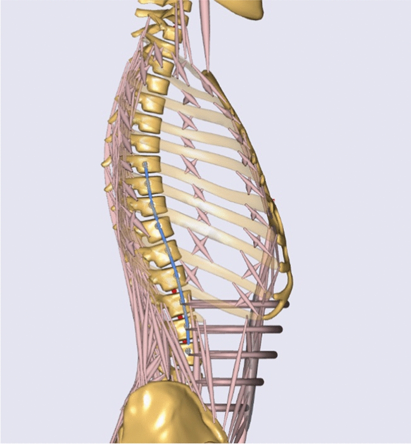
Musculoskeletal model of the spineFor this proof-of-concept study, AnyBody Modelling System was used as multi-body simulation software. Since there are no biomechanical cadaver experiments on scoliotic spines, it's difficult to validate a scoliotic spine model. Current static scoliotic MBS spine models [12,13,14] use EMG-measurement as validation tool. In order to simulate physiological movements, a health-shaped, validated spine model with integrated tether was used in this proof-of-concept study to objectify the raw data as a first step (Fig. 1). This approach also allows to compare the calculated values with experimental results. Furthermore, a straight spine most closely approximates the desired postoperative outcome.
Fig. 1
Lateral view of the VBT spine model with integrated tether device (blue) between T7-L3
The model is based on an existing, experimentally validated thoracolumbar spine model with articulated ribcage developed by Ignasiak et al. [15, 16]. Briefly, this model represents pelvis with sacrum, lumbar and thoracic vertebrae, ribs and sternum as rigid bodies. Spherical joints are defined between the individual vertebrae, revolute joints between the vertebrae and the ribs, and 6 DOF joints between the ribs and the sternum. Several hundreds of muscle fascicles represent the musculature of the main muscle groups of the thoracolumbar spine and ribcage. The elastic effects of intervertebral discs, paraspinal ligaments, and ribcage elastic properties are defined in the rotational stiffness in the spherical joints. This model allows to analyze static and dynamic spinal loads for various postures, tasks, and modeled spinal conditions.
The validated spine model has been extended in three ways. First, additional representative movement tasks are implemented in the existing model allowing to simulate not only flexion–extension (70°– 0° –20°), but also lateral bending (50°–0°–50°), and axial rotation (50°–0°–50°). Second, the relative contribution of the thoracic and lumbar spine to the total spinal ROM has been redefined based on [17,18,19]. Third, an individually adjustable tether system with realistic material properties has been implemented.
Material model for the tethering systemThe modelled VBT device consists of several individually adjustable and modifiable components, linking consecutive vertebral bodies (Fig. 1). The tether cord is represented in the spine model as linear elastic element. Monoaxial screws are fixed laterally in the desired vertebral bodies and are defined as attachment points of the tether cord. Then, the screws are tethered in the virtual model with a flexible 4 mm diameter tether cord.
To compare the effects of more ventral and dorsal screw positions, the screw position can be varied in the antero-posterior direction. The tether stiffness and pre-tension can be defined individually for each spinal segment. In the performed simulations, the tether stiffness and pre-tension has been assumed the same along the tethered spinal region. A global, realistic tether stiffness of 9000 N/m has been used for all the simulations [8].
The tether force \(_\) (N) is calculated by a linear equation of elasticity (Eq. 1). Due to the assumption that the tether can only transfer tension forces, the tether force is zero when the cord is not tensioned (i.e., below or at slack length). For the case that the tether is pretensioned, the tether transfers also normal forces when it is compressed below its slack length. For that, the calculation of the limit length change is introduced (Eq. 2).
$$f_ = \Delta L \cdot E_ \left\c} ^ \to \Delta L = 0} \\ ^ \to \Delta L = \left| \right| } \\ \end } \right.$$
(1)
$$with\; _:\, tether\,force\; [N];\,\,\Delta L:\, length \, change\; [m];\, _: tether \, stiffness\; \left[\frac\right]$$
$$\Delta \hat^ = \frac }} }}$$
(2)
$$ \begin&with\; }^: limit\; length\; change\; [m]; \\&_: pre}tension \;force\; \left[N\right]\end $$
SimulationsSeveral representative motion tasks have been simulated with and without a tether device (Fig. 2). For the simulations, the model spine has been representatively tethered between T7-L3 on the right side of the spine. (Table 1).
Fig. 2
Illustration of the VBT spine model during different physiological movements. Lateral bending, flexion–extension and axial rotation were simulated to represent the various possible postoperative movements
To investigate the effect of pre-tensioning, four tether pre-tension levels have been analyzed [8, 11]. (Table 1) The resulting tether forces and intervertebral compression forces were compared during different motion tasks [20]. In these analyses, the antero-posterior position of the screw has been aligned with the position of the vertebral joint and therefore considered as neutral.
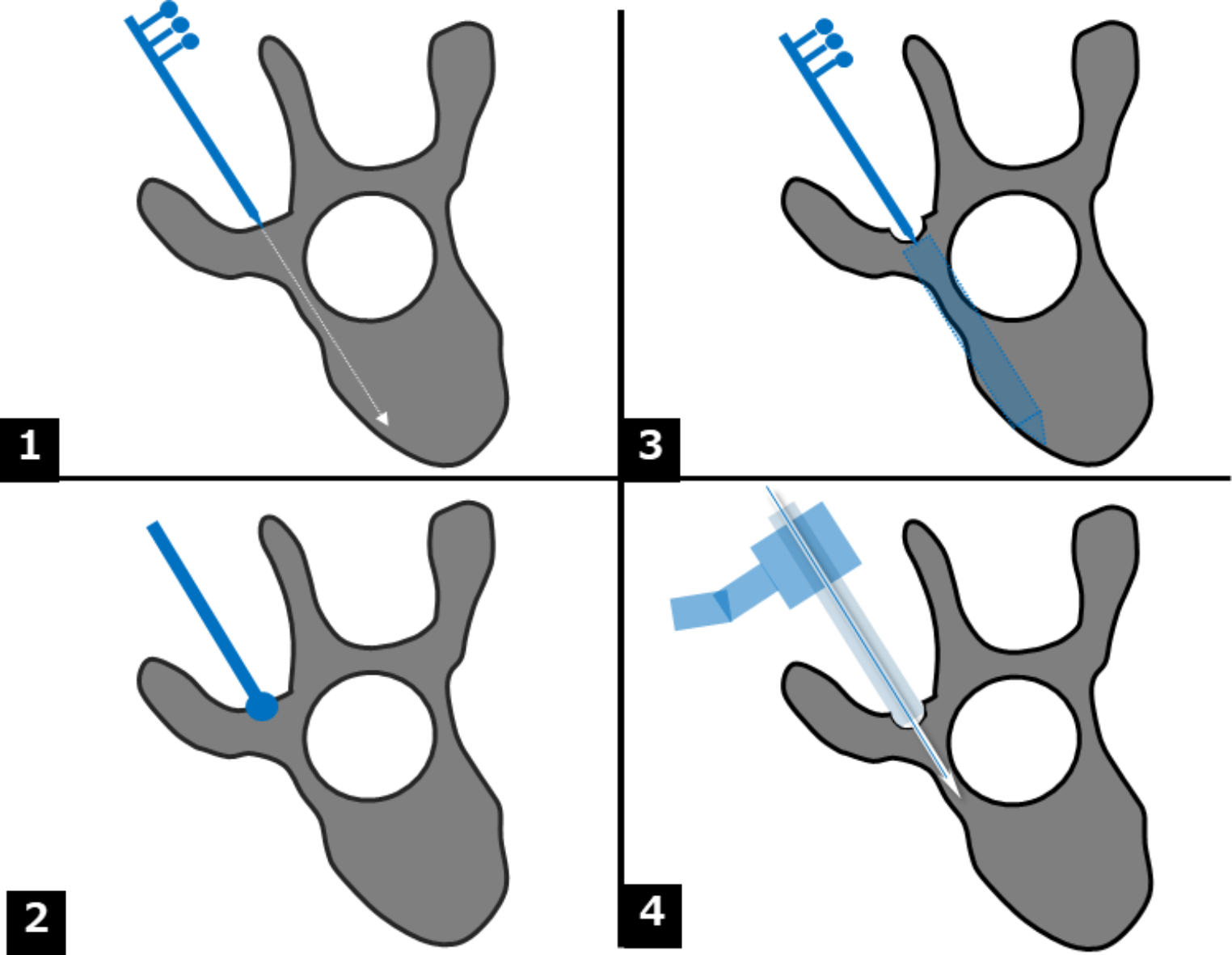
The effect of antero-posterior screw positioning on the tether force has been evaluated for the following simulated positions (Fig. 3): the reference neutral position, 0.5 cm more ventral, and 0.5 cm more dorsal.
Fig. 3
Illustration of the different screw positions analyzed at spine level
留言 (0)