
記住我


Each eye has its 3D orientation controlled by six extraocular muscles.1 Each eye rotates horizontally (adduction and abduction), vertically (elevation and depression), and torsionally (intorsion and extorsion). In normal binocular vision, these muscles work in tandem, aligning the eyes in a wide range of gaze directions, facilitating the fusion of the images from the two eyes, and hence allowing stereo depth perception.2 This natural ability can be compromised when one or more of the extraocular muscles do not function normally, resulting in strabismus. For example, a stroke can cause damage to the trochlear nerve,3,4 which innervates the superior oblique muscle, resulting in excess extorsion and adduction of the affected eye. If the left eye is affected in this way, its image appears shifted to the left and rotated clockwise with respect to the right eye's image. The actions of the various extraocular muscles are generally not independent, and with incomitant strabismus, the direction and extent of misalignment may vary significantly with the gaze direction.5 Measurement of eye misalignment in strabismic patients may be performed by orthoptists or optometrists using various instruments, including refracting prisms, the double Maddox rod, and the synoptophore,6 the latter two being able to measure torsional misalignment.
Typical noninvasive mitigation of strabismus-related double vision involves either occluding one eye at a time (with an eye patch or frosted glasses) or attaching Fresnel prism lenses7 to glasses. The former alleviates double vision but does not allow for binocular depth perception. The latter can be effective in restoring binocular depth perception, provided that the amount of torsion is sufficiently low (i.e., the misalignment is predominantly horizontal and/or vertical).
In strabismus clinical practice, press-on Fresnel prisms7 may be prescribed to mitigate binocular double vision caused by strabismus. For example, a patient with excess adduction but without severe vertical or torsional misalignment may be prescribed glasses with prisms acting horizontally. In this case, a lower prism diopter power is needed for close-range viewing and a higher power for long-distance viewing. Vertical misalignment (or a combination of horizontal and vertical misalignment) can similarly be mitigated using such prisms. With incomitant strabismus, prisms may be effective only in a limited range of gaze directions.7 Furthermore, these prisms alone cannot mitigate torsional misalignment. Significant torsional misalignment can cause discomfort and be a barrier to successful binocular fusion.7
Surgical interventions for strabismus include repositioning of the attachment points of one or more of the extraocular muscles, thus adjusting their action and so altering the eye alignment. The outcome of such surgical interventions cannot be predicted with certainty, and it is often the case that a surgical procedure can reduce some axes of misalignment in some gaze directions but increase misalignment in others.8 Another form of intervention is botulinum toxin injections to selectively paralyze one or more of the extraocular muscles. Botulinum toxin procedures also carry risks and may not produce the desired alignment outcome.9
A practical wearable apparatus, which is able to correct misalignment in all three axes (horizontal, vertical, and torsional), without potentially risky surgical intervention, could be of great benefit to patients presenting with certain forms of double vision, restoring their stereo vision and fine depth perception and potentially improving their quality of life. To the best of the authors' knowledge, there is currently no commercially/publicly available wearable optical system that is able to correct for torsional double vision.
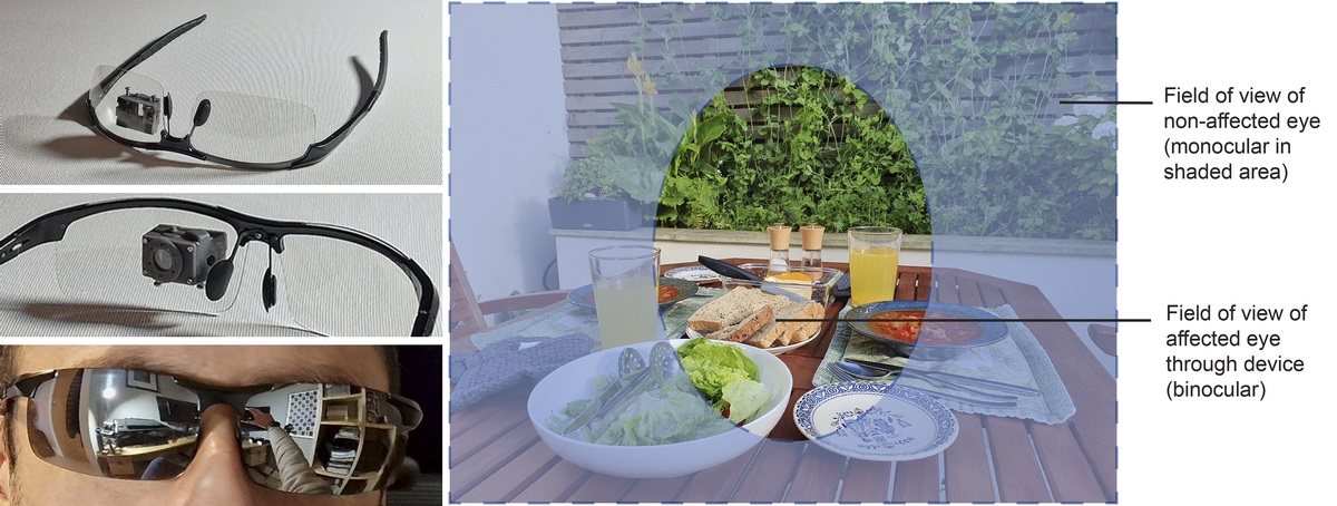
We propose a novel wearable optical apparatus that facilitates full binocular vision within a central viewing window, correcting for arbitrary horizontal, vertical, and torsional misalignment of the eyes. The area surrounding the viewing window in the affected eye is occluded. The full natural field of view is maintained in the nonaffected eye (Fig. 1).
 FIGURE 1:
 Left: two prototypes of the proposed wearable apparatus for correcting visual alignment. Left top and center: device mounted on glasses with clear lenses for use in dimly lit environments. Left bottom: device worn behind sunglasses for discreet everyday use. Right: schematic illustration of the field of view afforded to the patient when wearing the device. The affected eye views a central region of the scene (with corrected alignment), while the full field of view is maintained in the other eye. The patient is thus able to enjoy binocular vision in the central field of view and monocular vision in the periphery. Note that the location of corrected field of view is fixed with respect to the glasses and does not track the gaze of the patient; to view a different part of the scene in stereo, they must move their head.
The 3D rotational shift required to correct visual misalignment caused by strabismus could, in principle, be implemented using an electronic augmented/virtual/mixed reality headset with onboard “pass-through” cameras,10 by using custom onboard software to transform the live camera feed presented to the wearer. We propose implementing the required 3D rotational shift optically, in a compact, lightweight wearable device, which is not subject to the image quality limitations imposed by camera and display technology. Moreover, because it is camera-free, it could be used in situations where the use of cameras is prohibited.
METHODSThis research was reviewed by an independent ethical review board and conforms with the principles and applicable guidelines for the protection of human subjects in biomedical research.
The proposed apparatus comprises an assembly that houses two small front-silvered mirrors and a Fresnel prism positioned in front of the affected eye in such a way that the view is shifted horizontally, vertically, and torsionally so as to bring the image seen by the affected eye into alignment with the nonaffected eye.
Labeled 3D computer-aided design drawings of the apparatus are shown in Fig. 2. The direction and magnitude of the alignment correction parameters on each axis can be independently controlled by making small adjustments to the orientations of the mirrors and Fresnel prism to correct for arbitrary eye misalignment parameters.
 FIGURE 2:
 3D design of proposed wearable apparatus for correction of visual alignment. Top left: orthographic views showing details of optical assembly and optical path from the scene to mirror A, mirror B, and the Fresnel prism. Top right: adjustment mechanism allowing all three modes of alignment correction to be set independently (see text for details). Bottom: exploded view.
The orientations of the mirrors are field adjustable using two small screws. This two-mirror configuration allows the scene to be viewed without being flipped. The adjustment mechanism allows for precise subdegree adjustments to be made by hand, which would not be possible if the mirror orientation were to be adjusted directly. Mirror A controls both the vertical and torsional alignment, mirror B controls the horizontal alignment, and the Fresnel prism controls vertical and horizontal alignment. The Fresnel prism is required in addition to the two mirrors because the vertical and torsional shifts introduced by mirror A are coupled; i.e., adjusting the torsional alignment simultaneously adjusts the vertical alignment. Fig. 3 shows the effect of the three adjustment angles on the net alignment correction characteristics. The adjustment angles are specified relative to the nominal orientations of the respective elements (Fig. 2). The inherent coupling between these adjustment parameters and the resulting visual alignment correction is such that the device needs to be set in the following order:
 FIGURE 3:
 Characteristics of the visual alignment correction in the horizontal, vertical, and torsional axes as a function of the adjustment angles of mirror A (top), the Fresnel prism (center), and mirror B (bottom). The plot for the Fresnel prism is for a prism diopter value of 20 (the magnitude of the shift produced being 11.5°, the amplitudes of the sinusoidal curves are proportional to the strength of the prism used). Because of the coupling of axes, adjustment of the alignment needs to be performed in the following order: mirror A, Fresnel prism, and mirror B. The dashed horizontal lines indicate adjustment for a representative alignment configuration considered in the results section (refer to the text for details).
Adjust mirror A to achieve the desired torsional alignment (which also affects the vertical alignment and, to a small extent, the horizontal alignment); Adjust the Fresnel prism to achieve the desired vertical alignment (which also affects the horizontal alignment); and Adjust mirror B to achieve the desired horizontal alignment.The housing and movable internal parts of the optical assembly were designed in a computer-aided design environment, and a prototype was 3D printed. The optical assembly was mounted behind the lens of an off-the-shelf pair of glasses. Two versions of the prototype device were produced; one mounted to sunglasses, allowing for inconspicuous use in public; and the other mounted to glasses of the same design but with clear lenses, more suitable for use in dimmer indoor lighting conditions (Fig. 1). The frames need to be shaped such that there is sufficient room for the alignment correction device to be accommodated between the lens and the eye. Other frame designs could be used instead; however, designs such as tight “wraparound” sports frames would be unsuitable. Without affecting the operation of the device, glasses with optical focus correction could easily be used instead of plano lenses, if required by the patient, e.g., for myopia or hyperopia. These could, in principle, be bi- or varifocal lenses. No focus correction was required for the test patient in the experiments.
The optical assembly introduces a small translational shift in viewpoint in the affected eye. In the prototype design, the effective viewing distance is increased by approximately 4 mm, whereas the effective stereo baseline is reduced by approximately 8 mm. In normal binocular vision, the relative position of one eye with respect to the other changes according to gaze direction. To illustrate, consider that, when, e.g., gazing rightward (into the distance), with respect to the gaze direction, the left eye is positioned further back and closer to the right eye than in primary position. Such inherent changes in geometry are accommodated by the visual system in normal binocular vision, and therefore, we do not expect the slight viewpoint shift introduced by the alignment correction device to be problematic.
The size of the mirrors affects the field of view of the corrected image. In this implementation, circular mirrors of diameters 12.7 mm and 10.0 mm are used for mirrors A and B, respectively. Larger mirrors, although potentially increasing the field of view, would be difficult to accommodate behind glasses and would need to be mounted further apart, which could introduce excessive translational viewpoint shift. In patients with incomitant strabismus, a larger field of view would cause misalignment and hence double vision with gaze far from primary position, due to the variation in strabismus parameters with gaze direction. However, varying gaze direction within the relatively small field of view of the device causes relatively small changes in strabismus parameters, allowing binocular fusion to be maintained. When gazing outside of the field of view (in which case the view of the scene in the gaze direction is occluded), the view through the device may be less well aligned but is, ipso facto, in the periphery of the visual field.
RESULTSThe prototype device was designed to be used on the left eye (leaving the right eye view unaltered). In the results presented in this section, for simplicity, the left eye is referred to as the “affected eye,” and the alignment directions are specified correspondingly. To correct misalignment of the right eye, a horizontally flipped version of the design would be used (with the sign of the corrections being opposite to the left eye case, where applicable).
Prior to the fabrication of the prototype wearable device, optical simulations were performed using ray-traced rendering of a model of the device in computer graphics software.11 Such ray-traced rendering allows for physically accurate simulation of light transport and image formation, including accounting for reflection and refraction. The simulation allowed for verification of the functioning of the design. Fig. 4 shows simulated results for a representative strabismus configuration. In this configuration, the affected eye has excess adduction and extorsion, which results in the image being offset left and clockwise.
 FIGURE 4:
 Computer graphics-simulated results of the visual alignment correction performed by the proposed device for a representative strabismus configuration: horizontal, 7°; vertical, 0°; and torsional, 10°. From left to right: the misaligned naked-eye view, the view through the device, and the reference target alignment.
The simulation also facilitated characterization of the strabismus correction parameters as a function of the device adjustment parameters. Fig. 3 shows how the horizontal, vertical, and torsional alignment varies with the adjustment of the orientations of mirrors A and B, and the Fresnel prism. On the device, the adjustment is performed using the screws and ring, as shown in Fig. 2 (top right and bottom). Note that, for practical values of the alignment correction angles, the mirrors are rotated only by a few degrees, making precise subdegree adjustability essential. Suitable alignment correction parameters may be established for a given patient using standard orthoptic assessment techniques.
For explanatory purposes, a representative adjustment configuration is shown with dashed lines in Fig. 3 and described in detail hereinafter. Suppose the following net alignment correction is desired for primary position: horizontal, +7°; vertical, 0°; and torsional, +10°. As can be seen from Fig. 3 (top), to achieve the required torsion correction, mirror A would be set at +6°, which would also produce a vertical shift of +6° and a horizontal shift of +1°. Referring to Fig. 3 (center), observe that, in general, there are two orientations of the Fresnel prism, which produce a given vertical shift. To counteract the +6° vertical shift produced by mirror A, a − 6° shift is required from the Fresnel prism. This can be achieved by setting the Fresnel prism at either 210° (thin dashed lines) or 330° (thick dashed lines). For the 210° case, the Fresnel prism introduces −10° of horizontal shift, requiring mirror B to be set at +8° (Fig. 3, bottom), which adds a horizontal shift of +16° to achieve the desired net horizontal shift (1 − 10 + 16 = 7). For the 330° case, the Fresnel prism introduces +10° of horizontal shift, requiring mirror B to be set at −2°, which adds a horizontal shift of −4° to achieve the desired net horizontal shift (1 + 10 − 4 = 7). Although either configuration could be used, it is advantageous to set the Fresnel prism such that mirror B ends up being set closer to its nominal position. This is because the usable field of view is slightly reduced as mirror B is moved away from its nominal position. Therefore, in this example, the Fresnel prism should preferably be orientated at 330°. In order to calibrate the alignment correction parameters currently set on the device automatically, a small camera and a coded chart are used in conjunction with software using established 3D computer vision techniques.12–15
The prototype device (as shown in Fig. 2) was designed such that the ranges of adjustments for the mirrors and prism are as shown in the plots in Fig. 3, enabling it to correct up to ±21° of torsion.
Fig. 5 shows representative real-world image characteristics of the prototype device. The test target (a grid with the angular coordinates of the vertices labeled and overlaid on some text) is clearly visible through the device. The usable field of view is approximately 18° horizontally and over 30° vertically. Within this central field of view, the integrity of the grid layout is maintained, and the text remains clearly legible. Because of the use of front-silvered mirrors, there is no ghosting in the image. There is a small amount of chromatic aberration visible in high-contrast areas of the image, which is due to the Fresnel prism. There is some spurious image content in the periphery (on the left and right sides of the viewing window). This is an artifact arising from the particular arrangement of the optical elements. It does not tend to be noticeable during everyday use but could, if necessary, be mitigated by introducing a suitably shaped occluding element surrounding the viewing window.
 FIGURE 5:
 Results of the visual alignment correction performed by the proposed device. A grid showing angular coordinates (x in red and y in blue), over a paragraph of text (gray), was displayed on a monitor and viewed using a small camera, fixed in position. Left: reference view (naked camera). Right: view through the prototype device (set for strabismus parameters, −8°; vertical, 1°; torsional, 8°). Observe that, in the central viewing window of the device, the integrity of the grid layout is maintained, and the text in the background is clearly legible.
 FIGURE 6:
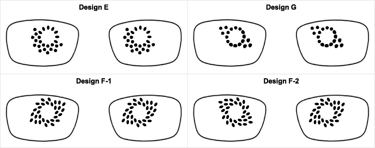
 Example left and right eye images presented by the offset stereo rendering software for verifying the patient's binocular fusion capability. The patient is required to identify the segment containing a protruding circle (in this example, it is in the upper segment). By design, the correct segment cannot easily be identified when viewing the left and right eye images independently.
The prototype device was evaluated on a single strabismic test patient. The test patient had a diagnosis of superior oblique palsy caused by damage to trochlear nerve sustained as a result of a hemorrhagic stroke, 3 years prior to the experiments. The patient presented with excess extorsion and insufficient abduction in the left eye (in primary position), necessitating the daily wearing of glasses with occluding frosting on one of the lenses to avoid double vision. Because of a high level of excess torsion present, the Fresnel prism glasses offered by the patient's strabismus clinic were not able to facilitate binocular fusion. However, the patient was able to achieve binocular fusion and stereo depth perception when presented with suitably rotationally shifted imagery generated using custom stereoscopic rendering software, viewed using standard anaglyph or polarization-based stereo glasses. We refer to this test setup as offset stereo rendering. The patient was presented with various mono- and stereoscopic photographs and video clips rendered using the offset stereo rendering system. In order to verify that the patient was experiencing binocular fusion, rather than simply suppressing one eye, a custom verification target (inspired by random dot fusion tests used in clinical practice16) was generated in the software and overlaid on the displayed imagery (Fig. 6). In the left eye image, a small disparity is applied to a circular region within one segment of the square random dot pattern, such that, with binocular fusion, it would appear to protrude. The dot pattern and the segment containing the displaced region were randomized for each successive image or video clip displayed. The patient was required to identify the segment containing the protruding circle using a keyboard. With the rendering offsets set according to the patient's strabismus parameters, the patient reported a comfortable viewing experience, seeing a single image, and perceiving depth within the stereoscopic content, and crucially, the patient was consistently able to select the correct segment in the verification target. We thus infer that they were achieving binocular fusion and not suppressing one eye. Conversely, when the patient was presented with content rendered with zero or arbitrary stereo offset parameters, they reported seeing a double image without perceiving depth, and they were not able to identify the correct segment in the verification target. The success of these offset stereo rendering experiments motivated the ideation and realization of the proposed wearable optical device for visual alignment correction.
After the prototype device was manufactured, it was adjusted for the test patient according to their misalignment characteristics (in primary position, where the viewing window covers the central region of the visual field). At this initial setup session, it was established that the patient was able to achieve comfortable binocular fusion while wearing the device. This was verified using the offset stereo rendering system described in the previous paragraph with zero offset (with polarization-based stereo lenses worn over the proposed alignment correction device). Thereafter, the test patient was given the device to wear regularly, at their own discretion, at home and out and about. Prior to this, the patient was advised to discontinue wearing of the device in case of any discomfort (including from any double vision) and not to wear the device for safety critical tasks. The clear-lensed version was used indoors, whereas the sunglasses version was used outdoors. Indoors, it was used for everyday household tasks, including cooking, eating, household chores, computer work, watching TV, and reading books. Outdoors, the device was used during social occasions, walking, jogging, and cycling on off-road paths. The patient reported that they found the device comfortable to wear and perceived certain close-range fine motor tasks (such as soldering) to be easier to perform while wearing the device. The patient reportedly used the device 3 to 5 days a week for 4 to 8 hours per day over a period of 6 months.
DISCUSSIONThe prototype optical assembly is lightweight. Including 3D-printed moving parts and housing, optical elements, and fasteners, the assembly weighs just 3.6 g (about the weight of half a cherry). The glasses they are mounted to weigh 27.0 g. The all up weight is thus 30.6 g, well within a comfortable weight range for glasses.
To date, the device has been subjectively tested on only one strabismus patient, without a formal study protocol. Although the results of this limited evaluation are encouraging, further evaluation is required to more fully characterize the performance of the device (including performance on standard clinical tests for fusion and stereopsis16) and to identify any potential issues. In the future, we intend to conduct a formal user study to evaluate the device with a cohort of several strabismic patients. Specifically, it would be instructive to obtain feedback regarding their acclimatization, perceived comfort, and the effect of wearing the device may have on their ability to perform a range of everyday tasks. It would also be of interest to investigate the extent by which, with regular wearing of the device, the visual system might gradually be retrained to achieve binocular fusion with progressively reduced levels of correction applied.
Wearing the apparatus has the potential to benefit people living with double vision from torsional strabismus, allowing them to regain a degree of binocular stereo vision, potentially making both everyday and specialized tasks requiring precise depth perception less challenging.
REFERENCES 1. Standring S, ed. Gray's Anatomy: The Anatomical Basis of Clinical Practice, 41st ed. Philadelphia, PA: Elsevier; 2015:670–5. 2. Ding J, Levi DM. A unified model for binocular fusion and depth perception. Vision Res 2021;180:11–36. 3. Joo W, Rhoton AL Jr. Microsurgical anatomy of the trochlear nerve. Clin Anat 2015;28:857–64. 4. Lee SH, Park SW, Kim BC, et al. Isolated trochlear palsy due to midbrain stroke. Clin Neurol Neurosurg 2010;112:68–71. 5. Bronwyn Bateman J, Isenberg SJ. Strabismus [abstract]. In: Reference Module in Biomedical Sciences. Philadelphia, PA: Elsevier; 2014. 6. Liebermann L, Hatt SR, Leske DA, et al. Comparison of methods for measuring cyclodeviation. Am J Ophthalmol 2021;224:332–42. 7. Kaur K, Gurnani B. Fresnel prisms. In: StatPearls; 2023. Available at: https://www.ncbi.nlm.nih.gov/books/NBK580488/. Accessed February 29, 2024. 8. Kushner BJ. The efficacy of strabismus surgery in adults: A review for primary care physicians. Postgrad Med J 2011;87:269–73. 9. Bort-Martí AR, Rowe FJ, Ruiz Sifre L, et al. Botulinum toxin for the treatment of strabismus. Cochrane Database Syst Rev 2023;3:CD006499. 10. Apple. Apple Vision Pro. 2024. Available at: https://www.apple.com/apple-vision-pro/. Accessed February 15, 2024. 11. Blender Online Community. Blender — a 3D modelling and rendering package. 2023. Available at: http://www.blender.org. Accessed December 23, 2023. 12. Zhang Z. Flexible camera calibration by viewing a plane from unknown orientations. Proceedings of the Seventh IEEE International Conference on Computer Vision; September 20-27, 1999; Kerkyra, Greece. 666–73. Available at: https://ieeexplore.ieee.org/stamp/stamp.jsp?tp=&arnumber=791183. Accessed February 29, 2024. 13. Bradski G. The OpenCV Library. 2000. Available at: https://opencv.org. Accessed December 23, 2023. 14. Detection of ChArUco boards. 2023. Available at: https://docs.opencv.org/3.4/df/d4a/tutorial_charuco_detection.html. Accessed December 23, 2023. 15. Garrido-Jurado S, Muñoz-Salinas R, Madrid-Cuevas FJ, et al. Automatic generation and detection of highly reliable fiducial markers under occlusion. Pattern Recognition 2014;47:2280–92. 16. Ester Han MH, Duckman RH, Clinical tests of fusion and stereopsis. 2016. Available at: https://entokey.com/clinical-tests-of-fusion-and-stereopsis. Accessed February 15, 2024.
留言 (0)