
記住我
Objective. Minimally invasive neuromodulation therapies like the Injectrode, which is composed of a tightly wound polymer-coated Platinum/Iridium microcoil, offer a low-risk approach for administering electrical stimulation to the dorsal root ganglion (DRG). This flexible electrode is aimed to conform to the DRG. The stimulation occurs through a transcutaneous electrical stimulation (TES) patch, which subsequently transmits the stimulation to the Injectrode via a subcutaneous metal collector. However, it is important to note that the effectiveness of stimulation through TES relies on the specific geometrical configurations of the Injectrode-collector-patch system. Hence, there is a need to investigate which design parameters influence the activation of targeted neural structures. Approach. We employed a hybrid computational modeling approach to analyze the impact of Injectrode system design parameters on charge delivery and neural response to stimulation. We constructed multiple finite element method models of DRG stimulation, followed by the implementation of multi-compartment models of DRG neurons. By calculating potential distribution during monopolar stimulation, we simulated neural responses using various parameters based on prior acute experiments. Additionally, we developed a canonical monopolar stimulation and full-scale model of bipolar bilateral L5 DRG stimulation, allowing us to investigate how design parameters like Injectrode size and orientation influenced neural activation thresholds. Main results. Our findings were in accordance with acute experimental measurements and indicate that the minimally invasive Injectrode system predominantly engages large-diameter afferents (Aβ-fibers). These activation thresholds were contingent upon the surface area of the Injectrode. As the charge density decreased due to increasing surface area, there was a corresponding expansion in the stimulation amplitude range before triggering any pain-related mechanoreceptor (Aδ-fibers) activity. Significance. The Injectrode demonstrates potential as a viable technology for minimally invasive stimulation of the DRG. Our findings indicate that utilizing a larger surface area Injectrode enhances the therapeutic margin, effectively distinguishing the desired Aβ activation from the undesired Aδ-fiber activation.
Neuromodulation devices, such as spinal cord and dorsal root ganglia stimulators hold great potential for treating debilitating chronic pain, which is one of the largest public health challenges in the United States, affecting over 100 million Americans and accounting for more than $600 billion in healthcare cost and lost productivity [1, 2]. The goal of neurostimulation therapies is to apply exogenous electric fields to the nervous system to elicit a desired therapeutic response and improve quality of life. Conventional pain management approaches, including the use of opioids, have unfortunately contributed to a concerning rise in addiction and subsequent fatal overdoses. Recent data shows a doubling in overdose cases, underscoring the urgent necessity for alternative and non-addictive pain therapies [3–5].
Spinal cord stimulation (SCS) has been a widely used neurostimulation therapy for treating intractable neuropathic pain in the trunk and limbs [2]. SCS involves implantation of one or more electrode arrays in the spinal epidural space and applying brief electrical impulses to create analgesia, putatively through pain-gating mechanisms within the spinal cord [6, 7]. Despite the widespread success of SCS in treating several chronic pain conditions, pain in specific areas, such as the groin, foot, low back, and knee, can be difficult to target due to the complex anatomy of the spinal cord. Several other factors, such as posture-related motion of the spinal cord in the thecal sac, lead migration, and electrical shunting in the cerebrospinal fluid (CSF), can limit successful neural targeting with SCS [3, 8, 9]. Therefore, for patients with pain in regions that are difficult to target with SCS, dorsal root ganglion stimulation (DRGS) can be considered as a viable alternative [3–5].
The dorsal root ganglion (DRG) is located near or within the foramen in the posterior spinal root at each level of the spinal cord. Each DRG contains the cell bodies of all the primary sensory neurons, and a portion of the axons innervating a single dermatome [10]. DRG neurons are pseudounipolar: a single axon process extends from the soma, bifurcates at a large node of Ranvier called the T-junction, and forms an axon that projects to the spinal cord and an axon that extends to the periphery [11]. Due to the precise targeting of a single dermatome's primary afferents, DRGS can provide patients with focal, dermatome-specific pain relief. In contrast to SCS electrodes which are placed along the dorsal aspect of the spinal cord, DRGS involves implantation of the annular electrode arrays in the intraforaminal space next to the DRG. DRGS was approved by the US Food and Drug Administration in 2016 to treat intractable complex regional pain syndrome of the lower limbs [12] and has been subsequently used for several other pain etiologies (e.g. phantom limb pain, painful diabetic neuropathy, groin pain) [13–16]. Early reports showed that due to the compactness of the intraforaminal space and scarcity of CSF around the ganglion [17], DRGS electrode arrays may be less prone to the type of lead migration and postural effects that can decrease the efficacy of SCS [18].
Both SCS and DRGS are limited by the procedures required to implant leads in epidural space. This process can be uncomfortable for patients, and permanent implants often require the use of general anesthesia. Additionally, recent clinical reports have shown significant DRG lead migration at the sacral level when using a transforaminal approach [19, 20], and several studies have reported other complications, such as pain near the implantable pulse generator (IPG) and lead fracture [21–23], resulting in some countries pausing DRGS implantations. Thus, to achieve improved clinical implementation and to reduce complexity to minimize the failure points, a minimally invasive procedure is needed to deliver effective stimulation without the drawbacks of existing electrode technologies and their placement procedures.
The Injectrode is a tightly wound polymer coated platinum/iridium microcoil which is injected via an 18-gauge needle near a neural target where it forms a highly conforming, flexible, clinical-grade electrode platform [24, 25]. The Injectrode consists of three continuous regions: an uninsulated portion at one end to serve as a stimulation site, an insulated lead portion in the middle, and another uninsulated portion at the other end to serve as a subcutaneous charge collector [26]. During delivery, the Injectrode can fold into a variety of conformations dependent on the target anatomy. The delivered electrode is therefore larger in diameter than the needle from which it was deployed, thereby reducing the chances of migration. Once the Injectrode is delivered to the target structure, then the insulated lead is extruded back to the superficial tissue layers where the subcutaneous charge collector is placed [26, 27]. Electrical current is delivered transcutaneously to the charge collector located directly beneath the skin surface using noninvasive skin adhesive patch electrodes, eliminating the need for IPGs or wires perforating the skin. From the charge collectors, the electrical currents then travel through the insulated lead wire to the Injectrode situated on top of and near the DRG in the intraforaminal space (figures 1 and A1). Thus, it is important to understand the charge delivery pathway in this electrical stimulation system because it directly affects the safety and effectiveness of the therapy.
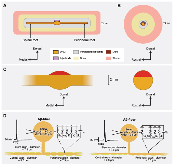
Figure 1. Representative schematic of our finite element method (FEM) model of DRGS. We developed an FEM model of a DRG and surrounding anatomy. Two separate versions of this model were developed and scaled to fit dimensions of the feline L7 DRG and human L5 DRG. (A) Side view of the DRG with the Injectrode oriented above the ganglion. (B) Cross-sectional view through the middle of the DRG and Injectrode. (C) Red-shaded regions indicate the locations of the somata of primary sensory neurons in sagittal and transverse DRG cross sections. (D) Multicompartment models of primary sensory neurons, representing the pseudounipolar morphology of a large-diameter myelinated Aβ-fiber and a smaller-diameter thinly myelinated Aδ-fiber. An example action potential from each model neuron is shown on the left. The equivalent circuit diagram with active ion conductances included in the nodal, initial segment, and soma compartments is shown on the right.
Download figure:
Standard image High-resolution imageTo gain a comprehensive understanding of the charge delivery mechanisms employed by this system, it is important to first examine the impact of various technical and anatomical factors on the electrical stimulation delivered to the DRG. These factors include the size of the Injectrode and the relative placement and orientation of the patch electrodes and the collector. Although similar studies have been conducted on preclinical models of vagus nerve stimulation using the Injectrode [26], due to the substantial differences in geometry and anatomical positioning between the DRG and the vagus nerve, along with their respective surrounding soft tissues, the associated side effects exhibit considerable variation. When targeting the DRG, there is a potential risk of stimulating sensory Aδ-fibers, which can induce acute pain sensations. Thus, the effect of clinically adjustable parameters on neural recruitment during DRGS with the Injectrode system remains unclear. Therefore, leveraging computational modeling to bridge this knowledge gap could optimize the clinical efficacy of the system and enable the exploration of different configurations.
In this work, we implemented a computational modeling approach to investigate the effects of clinically relevant factors on neural recruitment during DRGS via the Injectrode. Our initial goal was to validate our computational modeling approach by comparing experimental measurements to the corresponding model predictions. Therefore, we first developed a computational model of DRGS in a feline model, compared and validated our model predictions to the neural recruitment observed in our previous experimental work [28]. After validating our computational modeling approach, we then developed a generalized model of stimulation of the human L5 DRG, a common stimulation target to manage chronic foot pain [14, 15, 29]. We used this clinical-scale model to examine how different shapes, sizes, and orientations of the Injectrode affected neural recruitment profiles within the DRG. Finally, we built a full body human model of bilateral DRGS with a complete bipolar Injectrode system, i.e. skin electrodes, collectors, microwires, and Injectrodes. We observed that for full body bipolar TES-collector-Injectrode stimulation, the activation thresholds were significantly lower for an Injectrode of larger surface area suggesting that placing the Injectrode such that it covers a maximal area possible may be the optimal configuration for activating relevant neural tissue because it led to an amplified therapeutic window differentiating the desired Aβ-fiber activation from undesired Aδ-fiber activation. In contrast, smaller Injectrode sizes exhibited characteristics more reminiscent of conventional SCS/DRG electrodes, resembling a point-source effect.
We developed computational models of DRGS to investigate how the model predictions compared to experimental data and how clinically controllable factors (e.g. Injectrode size) affect neural activation in the DRG. Since DRGS is believed to provide analgesia via pain-gating mechanisms induced by the activation of Aβ-fibers [3–5], we built computational models to study neural recruitment of Aβ-fibers within the DRG using the Injectrode. For the canonical and the full-body human-scale models, we also built computational models of Aδ-fibers to examine possible off-target effects induced by Injectrode stimulation. Previous modeling efforts demonstrated that DRGS at clinical amplitudes triggered responses from the putatively innocuous low-threshold mechanoreceptor (LTMR) Aδ-LTMRs, with activation observed in less than 40% of the overall population [5]. In contrast, the nociceptive high-threshold mechanoreceptor Aδ-HTMRs displayed minimal activation, affecting less than 10% of the entire population [5]. Therefore, in this study, we only modeled the Aδ-LTMRs. We coupled a finite element method (FEM) model of a lumbar DRG to multicompartment models of sensory Aβ- and Aδ-fibers [5]. We used the FEM model to calculate the potential fields generated by DRGS and applied these potentials to the multicompartment neuron models (figure 1). We examined the stimulation amplitudes required to activate Aβ- and Aδ-fibers placed throughout the dorsal aspect of the DRG. We also investigated how the neural recruitment profiles changed as a function of stimulus pulse width and Injectrode geometry.
We constructed three-dimensional FEM models using anatomical data from existing literature. We used previous computational modeling studies and experimental measurements [30–33] to assign electrical conductivities for each tissue type. We modeled each tissue as having an isotropic conductivity, except the nerve root, which we modeled as having an anisotropic conductivity (table 1).
Table 1. Electrical conductivities assigned to the anatomical components in the FEM models.
ParameterValue (S m−1)ReferencesGray matter0.230[31]White matter (Longitudinal)0.600[31]White matter (Transverse)0.083[31]Dural covering0.600[33]Bone0.020[30]General tissue0.250[31]Fat0.04[34]Encapsulation0.170[32]Skin0.148[35]Platinum9.43x106[36]To calculate the potential fields generated by DRGS, we used COMSOL Multiphysics (COMSOL, Inc., USA) and applied the relevant Dirichlet and Neumann boundary conditions. To simulate a canonical DRG model of monopolar configuration, we applied a unit current stimulation boundary condition (i.e. 1 A) to the surface of the Injectrode and set the outer boundaries of the general thorax domain to ground (i.e. 0 V). We used the conjugate gradient method to solve the Laplace equation:

where  is the tissue stiffness matrix and
  is the calculated electric potential.
We stimulated multicompartment models of primary sensory neurons found in the DRG using the NEURON simulation environment (v7.4) [37, 38]. We implemented previously published models of an Aβ-fiber (figure 1) [4, 5]. Following our previous work [4, 5], we set our Aβ-fiber model central axon diameter to 5.7 μm and the peripheral axon diameter to 7.3 μm [39]. The models had a soma 80 μm long and 80 μm wide, connected to a 7.3 μm diameter stem axon. The stem axon extended 789 μm before splitting into two axons. The myelinated compartments consisted of two concentric layers containing linear leak conductances with a parallel membrane capacitance. The nodes of Ranvier contained the parallel active nodal conductances of the sensory-specific axons described by [40]: fast Na+, persistent Na+, fast K+, and slow K+ ion channels. The active nodal conductances were modeled in parallel with a linear leakage conductance and membrane capacitance (figure 1(D)). The soma and initial segment contained the same active ion channels as the nodes, but with sodium channel densities of 300 channels μm2 and 500 channels μm2 [4, 5]. For the canonical and full body human models, we implemented the LTMR Aδ-fiber models that were also previously developed in computational modeling work from our group [5]. The thinly myelinated medium-diameter Aδ-fibers express distinct voltage-gated sodium channel profiles, namely Nav1.6, similar to other non-nociceptive myelinated mechanoreceptors [5]. Each Aδ-fiber model had a soma 29 μm long and 34 μm wide, connected to a 3.0 μm diameter stem axon. The stem axon extended 840 μm before splitting into two axons. One axon projected towards the spinal cord, with a diameter of 2.0 μm, while the other projected to the periphery and had the same diameter as the stem axon (i.e. 3.0 μm) (figure 1(D)).
We linearly interpolated the extracellular potentials calculated in equation (1) onto the middle of each compartment of the cell models. We applied the extracellular potentials to the multicompartment models using NEURON's extracellular mechanism within the Python programming language [38]. We calculated each compartment's time-dependent membrane voltage in response to DRGS by using a backward Euler implicit integration method with a time step of 5 μs (figure 2). The tissue conductivities of the FEM model were linear. Therefore, the potential field generated by a specific DRGS amplitude was a scalar multiple of the potential field generated by a unit (i.e. 1 A) stimulus. We calculated activation thresholds for biphasic pulses using a binary search algorithm with a resolution of 0.1 μA [4, 5].
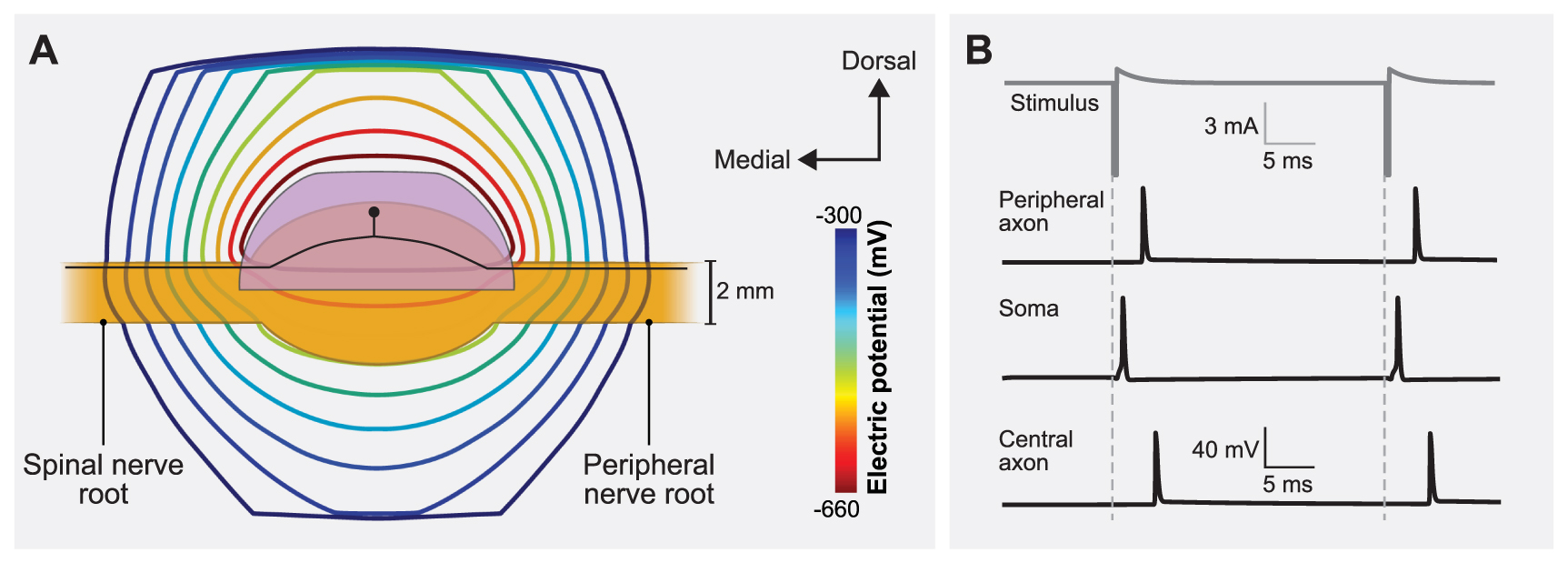
Figure 2. Coupling the finite element method (FEM) model of a human L5 DRG to the multicompartment models of primary sensory neurons. (A) Isopotential lines of the extracellular potentials generated by leading cathodic monopolar DRGS calculated from the FEM model. An example primary sensory neuron trajectory is shown in black with the soma below the Injectrode. (B) Time-dependent transmembrane voltages resulting from stimulating an example Aβ-fiber with a cathodic stimulus having a pulse amplitude of 6 mA, pulse width of 300 µs, and pulse frequency of 40 Hz. The action potential initiates near the soma and then propagates into the peripheral and central axons, as shown in the three traces.
Download figure:
Standard image High-resolution image 2.1. Feline model of DRGSTo validate our computational modeling approach, we developed a canonical computational model of monopolar stimulation of a feline L7 DRG with the Injectrode and subsequently compared our findings with a set of experimental results (see appendix A1) [28]. We constructed a three-dimensional FEM model (figure 1) based on measurements from previous computational modeling studies that utilized cadaver and imaging studies of the DRG and surrounding anatomy (e.g. dural covering, intraforaminal tissue, bone) (table 2) [4, 5, 41]. We built this FEM model in the 3-matic module within the Mimic Innovations Suite (Materialise, Belgium). We modeled the Injectrode to have a surface area of 48 mm2 that replicated the average size used in our previous experimental work [28]. We imported the volume mesh generated in 3-matic into COMSOL Multiphysics and applied 1 A at the Injectrode surface, grounded the outer surfaces of the model, and solved equation (1). We interpolated the model solutions into the center of each compartment of the multicompartment neuron models. We validated the model by comparing the minimum stimulation current required to invoke a response in the DRG neurons to the current needed to produce a measurable electroneurogram response in the preclinical experiments [28]. For each set of stimulation parameters, we calculated the minimum stimulus amplitude necessary to elicit one or more action potentials in each Aβ-fiber (i.e. the activation threshold). We populated the dorsal aspect of the feline L7 DRG with 1355 Aβ-fibers spaced 200 µm apart, with the somata lying near the dorsal surface (figures 3(A) and A2(A)). To mimic the experimental conditions, we used symmetric biphasic stimulus pulses applied at a frequency of 58 Hz and three different pulse widths of 80, 150, and 300 μs [28].
Figure 3. DRGS amplitudes required to elicit one or more action potentials (activation threshold) in Aβ-fibers for stimulation with an Injectrode in the feline model. (A) The contour plots show variation of activation thresholds along the dorsal-rostral plane and the dorsal-medial plane for three different pulse widths. The red shaded region indicates the location of the somata of the primary sensory neurons, enclosed by the Injectrode at the top. The dorsal-rostral cross section (top) is taken along the midline of the dorsal-medial view (bottom), marked by a dashed line, and vice versa. (B) Comparison of minimum activation thresholds generated by our computational model with the ECAP thresholds from the acute experiments (for two lumbar levels) across three different pulse widths [28].
Download figure:
Standard image High-resolution imageTable 2. Dimensions of the canonical FEM model of the feline L7 DRG.
ParameterValueReferencesDRG length6.50 mm[41]DRG width3.05 mm[41]Nerve root radius0.75 mm[41]Dural sheath thickness0.02 mm[41]2.2. Canonical human model of DRGSTo examine how the Injectrode geometry affects neural recruitment profiles during DRGS and assess its potential adverse effects associated with the activation of acute pain fibers, we developed a canonical model of DRGS applied to a human L5 DRG (figure 4(A)). We based the model geometry on our prior work (table 3) [4, 5], with the standard clinical annular DRGS electrode array replaced by the Injectrode. The FEM model schematic in figure 1 was scaled to represent the dimensions of a human L5 DRG (figure 4(A)). We varied the included angle covered by the Injectrode on the dorsal-rostral plane (ϕ) and dorsal-medial plane (θ) from 30° to 150° at an interval of 60°, thereby generating a total of nine different Injectrode geometries (table 4 and figure 4). The Injectrodes were embedded in a 300 μm thick encapsulation layer, to represent typical foreign body response to implanted materials [32]. As described in the previous sections, we developed an FEM model to mimic monopolar stimulation conditions and interpolated the model potential fields onto the center of each compartment of the Aβ- and Aδ-fibers within the human L5 DRG model. We uniformly populated the dorsal aspect of the L5 DRG with 1378 Aβ-fibers and 1378 Aδ-fibers spaced 300 µm apart along the entire dorsal half, with the somata lying near the dorsal surface (figures 1(C) and A2(B)). To mimic parameters used in clinical DRGS [4, 5], we utilized biphasic stimulation waveforms of a pulse width of 300 µs and a pulse frequency of 40 Hz.
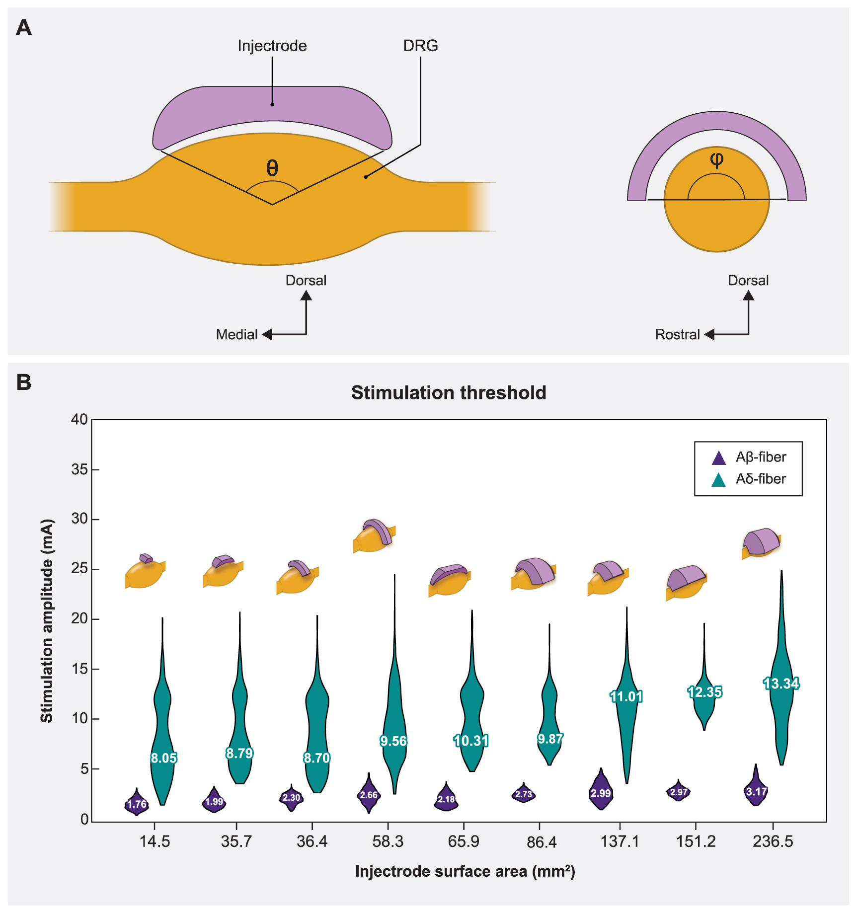
Figure 4. Sagittal and transverse cross sections of the DRG and the Injectrode indicating the various angles of coverage of the Injectrode and the corresponding mean activation thresholds. (A) The angles in both planes (θ,ϕ) varied from 30° to 150° at an interval of 60°, thus generating a total of nine models. (B) Plots showing comparison between the distribution of activation thresholds of Aβ- and Aδ-fibers generated by the various Injectrode geometries with the mean values inset and the corresponding Injectrode geometry at the top of each violin plot.
Download figure:
Standard image High-resolution imageTable 3. Dimensions of the canonical FEM model of the human L5 DRG.
ParameterValueReferencesDRG length9.40 mm[42]DRG width5.90 mm[42]Nerve root radius1.19 mm[43]Dural sheath thickness0.15 mm[44]Foramen height17.1 mm[42]Encapsulation layer0.30 mm[32]Table 4. Surface areas of the different Injectrode shapes.
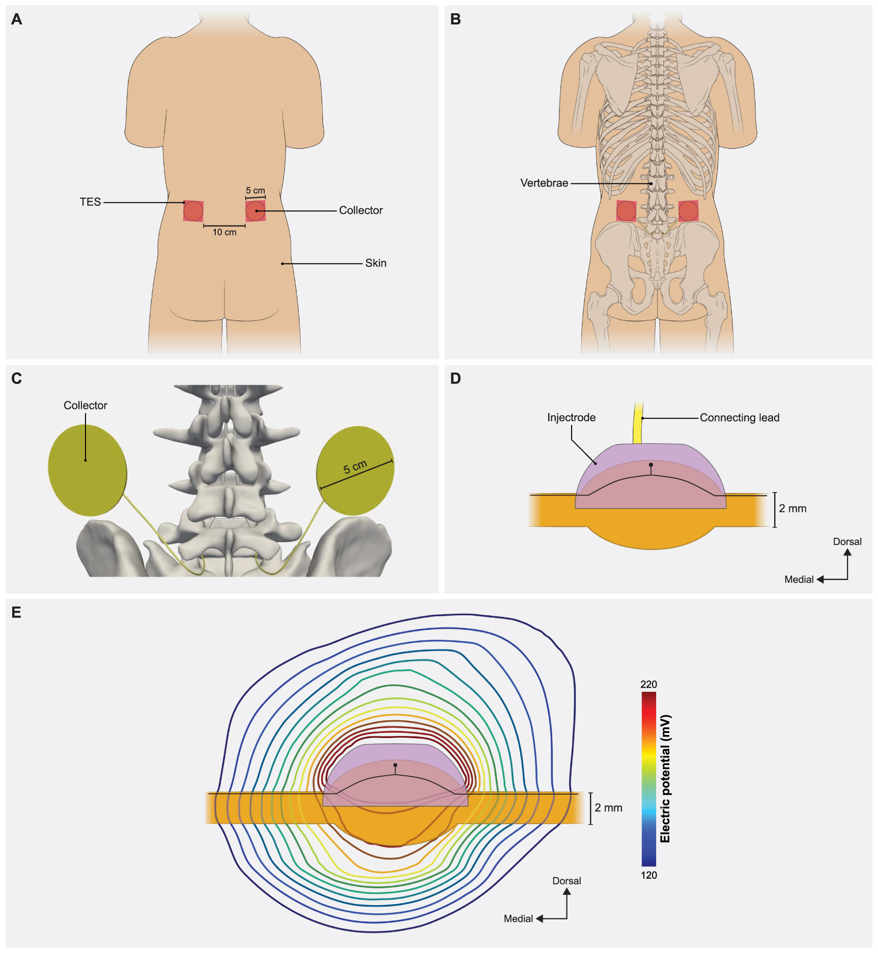
Dorsal-medial angle (θ) (degrees)Dorsal rostral angle (ϕ) (degrees)Surface area (mm2)303014.5903035.71503065.9309036.4909086.415090151.23015058.390150137.1150150236.5150180273.32.3. Model of clinical DRGS applied with a complete Injectrode systemOur final goal was to build a full-scale human model with bilateral lumbar DRG and corresponding spinal nerves to perform model-based design of the Injectrode system (figure 5). The primary model structures were based on the 'Duke' model from the IT'IS foundation virtual population models [45]. We modeled a skin layer with a uniform thickness of 2.64 mm [46] and a fat layer with a uniform thickness of 3.76 mm [47]. For simplicity, we modeled the fat and subcutaneous adipose tissue as a single layer [34]. To represent the rest of the soft tissues in the abdominal region, we assigned them the electrical conductivity of the general thorax [31] (table 1). Additionally, we included the entire thoracic, lumbar, and sacral vertebrae, along with the spinal cord, dura mater, and cerebrospinal fluid. To alleviate computational demands, our model focused solely on the L5 lumbar roots, as they are a common target for managing chronic foot pain [14, 15, 29]. The model is comprised of two transcutaneous electrical stimulation (TES) surface electrodes (side length 5 cm) placed equidistant from the central sagittal plane, with a 10 cm edge-to-edge distance, at the L2 vertebral level (figure 5(A)). Directly beneath the surface electrodes were circular collectors positioned at a depth of approximately 2 mm from the outer skin [26, 34]. These collectors (diameter 5 cm) were connected to the Injectrode that encompassed the L5 DRG via a 0.5 mm diameter wire (figure 5(C)). We assigned the collectors, wires, and the Injectrode the electrical conductivity of platinum (table 1). We insulated the wires and modeled a bipolar Injectrode system with one TES patch modeled as a current stimulus terminal and another set as ground (i.e. 0 V). In our model, a bipolar stimulation configuration involved having two Injectrodes positioned on the DRG on the opposite sides of the same spinal level (L5), each with its corresponding insulated wire, collector, and TES patch. The Injectrode-collector-TES system on the contralateral side acted as a return path (figure A4). We populated the dorsal half of the ipsilateral L5 DRG near the Injectrode connected to the collector beneath the active terminal with 1378 Aβ-fibers spaced 300 µm apart, with the somata lying near the dorsal surface (figures 1(C) and A2(B)). Additionally, to consider the possibility of generating acute pain sensations as a potential side effect of DRGS, we included thinly myelinated medium-diameter Aδ-fibers responsible for both noxious and innocuous sensations. The channel dynamics and morphological structure of these Aδ-fibers were modeled based on our previous work [5]. We included a total of 1378 Aδ-fibers spaced 300 µm apart along the entire dorsal half of the DRG, mirroring the distribution of Aβ-fibers. To mimic previous work with the Injectrode system [26], we determined the activation thresholds for DRG neurons in response to a symmetric biphasic stimulus with a pulse width of 250 µs applied at a pulse frequency of 25 Hz. We simulated DRGS with three Injectrode shapes, where the included angle varied as 30°, 90°, and 150° in the dorsal-medial plane and 30°, 90°, and 180° in the dorsal-rostral plane (table 4). The resultant surface areas of the Injectrode were: 14.5, 86.4, and 273.3 mm2, respectively (figure 6). We also encased the Injectrodes and collectors in a 300 μm thick encapsulation layer [32].
Figure 5. Full-body model with truncated arms, legs and neck with a charge delivery system mimicking clinical implementation of an Injectrode system. (A) Dorsal view of the body with transcutaneous electrical stimulator (TES) patch electrodes visible on the skin surface at the L2 vertebral level. In a bipolar configuration, one TES electrode serves as an active terminal and the other TES electrode is grounded. (B) Collectors are placed directly under the TES patch to receive some of the charge delivered to the TES electrodes. (C) The collectors deliver charge to the Injectrode using a connecting lead made of the same material and inserted in the spinal cavity using an interlaminar approach. (D) A side view of the Injectrode, DRG, and the connecting lead. The Injectrode sits right on top of the dorsal aspect of the DRG. An example primary sensory neuron trajectory is shown in black. (E) Isopotential lines of the potential field generated by the bipolar TES-collector-Injectrode system near the DRG with an example primary sensory neuron shown in black.
Download figure:
Standard image High-resolution imageFigure 6. The effect of Injectrode size on activation thresholds with the bipolar Injectrode DRGS configuration in the full-body model. (A) Raincloud plots show the variation of stimulation amplitudes for the entire population of model Aβ-fibers within the DRG. (B) Activation thresholds for the entire populations of Aβ- and Aδ-fibers using the Injectrode with the largest surface area (273.3 mm2) considered in this study.
Download figure:
Standard image High-resolution image 3.1. Model validationStimulus pulse width is a critical parameter when programming a patient's DRGS system and has been shown to affect neural activation [48] and paresthesia distribution [49] during SCS. Therefore, we scaled the canonical DRG model to match the dimensions of a feline L7 DRG and calculated primary afferent activation thresholds for several pulse widths (i.e. 80, 150, 300 μs) and a constant pulse frequency of 58 Hz [28] with the Injectrode centered above the ganglion in monopolar stimulation conditions. Figure 3 shows the activation threshold as a function of the three pulse widths. The activation thresholds were nearly consistent across the dorsal-rostral plane in a cross-section taken along the width of the DRG, because the Injectrode uniformly covers that area (figure 3(A)). However, along the dorsal-medial plane in a cross-section taken along the length of the DRG, the activation thresholds tend to increase with increasing distance of the axons from the Injectrode. This can be attributed to the larger distance between the neuron and the Injectrode (figure 3(A)). We also observed the expected decrease in activation thresholds for longer pulse widths (figure 3(B)).
To validate our modeling approach, we also compared the activation thresholds predicted with our computational model to the activation thresholds measured in our previous experimental research in a feline model of DRGS with the Injectrode [28], where the L6 and L7 DRG were exposed in four cats via partial laminectomy or burr hole. In this previous work, we stimulated the DRG with an Injectrode using biphasic pulses at three different pulse widths (80, 150, 300 μs) and pulse amplitudes spanning the range used for clinical DRG stimulation. We previously used nerve cuff electrodes to record antidromic evoked compound action potentials (ECAPs) in the sciatic, tibial, and common peroneal nerves. Then we determined the charge-thresholds and recruitment rates for ECAPs from Aα-, Aβ-, and Aδ-fibers (see appendix A1, figure A3). The minimum predicted Aβ-fiber recruitment thresholds from our models have a maximum mean absolute percentage error less than 37.5% of the values measured in these previous acute experiments [28].
3.2. Injectrode geometryUnderstanding the impact of changes in surface area on neural recruitment during DRGS is crucial due to the importance of contact surface area as a design parameter, particularly in the case of an Injectrode where the entire surface acts as an active contact and may vary from patient to patient. Therefore, we made nine distinct models with different Injectrode geometries. For monopolar stimulation applied with a stimulus pulse width of 300 µs and pulse frequency of 40 Hz, we observed that increasing the Injectrode surface area almost exclusively increased the mean activation thresholds of Aβ-fibers within the DRG (figure 4(B)). The one exception was when the surface area was increased from 58 mm2 to 66 mm2, during which a minor decrease in mean threshold amplitude was observed. It was also observed that for different models of Injectrode of similar area, the geometries which spanned longer in the dorsal-medial plane (figure 4(B)) had relatively lower amplitudes. There was no activation of Aδ-fibers at comparable activation thresholds. In some cases, irrespective of the size of the Injectrode, we observed a small percentage (<10%) of the acute pain fibers activated, when we stimulate the entire population of the Aβ-fiber mechanoreceptors (figure 4(B)).
3.3. Effect of clinical parameters on charge delivery via bipolar TES-collector-Injectrode systemThe Injectrode system employs TES electrodes that wirelessly transfer charge to subcutaneous collectors, which is the uncoated wire section of an Injectrode placed under the skin during the final step of the injection procedure. This non-invasive stimulation setup m
留言 (0)