
記住我

Ethical approval (eEMPS000388) was gained from the local research ethics committee at the University of Exeter to recruit healthy adult participants with no history of knee joint injury (5 males and 5 females) for knee joint magnetic resonance imaging (MRI). The average (± standard deviation) height, weight, and body mass index for the participants were 1.7 m (± 0.07), 76.8 kg (± 22.20) and 26.4 kg/m2 (± 6.20) respectively. Informed consent was obtained from all individual participants in the study. The knee joints of the participants were scanned in a supine position with a knee coil using a 3 Tesla MRI (Siemens, Prisma) to acquire T1 weighted images with a contrast that differentiated between soft tissue, cortical bone, and trabecular bone (see Table 1 for scanning protocol).
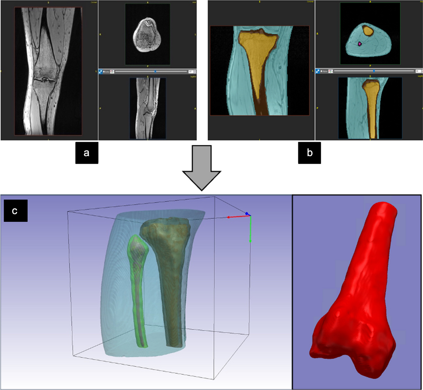
Table 1 MRI scanning protocol used for knee scansImage segmentation and modellingThe cortical and trabecular bones were segmented from the MRI DICOM images of the tibia and femur using ScanIP software (Synopsis Simpleware, Ver. 2020, Sunnyvale US) to create a 3D knee surface model consisting of cortical and trabecular compartments in every subject scan (Fig. 1). A threshold for image pixel intensity values was used to segment each compartment automatically which was then edited manually to delete any pixels segmented outside of the compartments. The surface models were then exported into stereolithography STL file format.
Fig. 1
a Coronal, sagittal, and axial, view of knee MRI scan of one of the participants. b Segmented cortical and trabecular bone of knee joint MRI Images. c the exported 3D STL model of the segmented cortical, trabecular bone of the knee joint
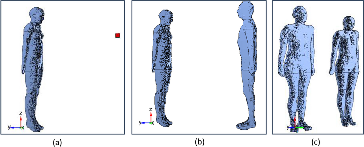
One average 3D shape and volume model of the tibia and femur was based on the five male models and the other one from the five female models was created using (Geomagic Wrap, v.2021; 3D Systems) which is a software capable of editing and creating 3D surface models. The average tibia model was created by loading the five male tibia surface models into the software and aligning them manually using the global registration and alignment functions. One of the male tibia models was fixed and used as a reference while the rest of the models were aligned using multiple registration points applied to several locations in each model (Fig. 2). After the alignment and registration of the five models, the averaging function in the software was used to calculate the geometry and the volume of the models and create a new average volume TKR model with conserved average geometry and distinct cortical and trabecular bone compartments. The process of the alignment, registration, and models averaging was repeated for the male femur and female tibia and femur models. 3D slicer Chitubox software [17] was used to apply inverse modelling to the cortical and trabecular compartments of the average male and female phantoms to turn the solid models into hollow ones with distinct hollow compartments. This was done using the hollow tool in the software to create compartments with a wall thickness of 1 mm and hollowing precision of 80% to make the internal walls smooth. This inverse modelling is to allow for injecting fluids into the model's compartments. Finally, a trabeculae model segmented from one participant's MRI scan was inserted inside the empty trabecular compartment of the average male and female TKR models to create porous trabecular structures mimicking human trabecular bone (Fig. 2). ScanIP and Geomagic Wrap were used for generating and editing the TKR model because as they were already available in the lab and the authors had prior knowledge of their use.
Fig. 2
Manual Alignment of the 5 male tibia models. a the reference model. b is one of the models being aligned. c the result of the alignment of all the tibia models. d 3D model segmented from trabecular bone structures
Modelling implant insertionA 3D model of the tibial TKR prosthesis was created by scanning it using Polycam software with an iOS phone camera that employs light detection and ranging technology (LiDAR) [18] to create 3D models. This method is applied by continuous image capturing while rotating the prosthesis to cover it from multiple angles and reconstructing the images to create a 3D image. The 3D scan was performed by placing the prosthesis on a rotator and fixing the camera at a distance of 10 cm in a well-lit room. The prosthesis was then flipped and rotated again to cover its upper and lower sides. The tibia metal compartment model was created successfully with a similar shape to the real one with high accuracy but with a smaller size. This model was later edited, smoothed, and scaled to match the dimensions of the physical one using Geomagic wrap. However, capturing the femur metal compartment was not successful, probably due to the high irregularity of its shape which causes images to overlap at some angles and corrupt the final 3D reconstruction. To solve this problem, the geometries of the femur TKR prostheses were measured and drawn manually using SolidWorks software to create a 3D model. These CAD models were then used for the virtual TKR surgery, in which it was inserted into the average knee models, creating the insertion site by Boolean operations. This approach created a void volume for the physical insertion of the knee prosthesis which would be used in the phantom scan (Fig. 3).
Fig. 3
a Physical femur and tibia prostheses. b a 3D surface model of the tibial prosthesis metal compartment. c a 3D surface model of the femur prosthesis metal compartment
The final step was to undertake virtual TKR surgery on the average male & female 3D models using the Chitubox software to merge the metal prostheses with the anatomical models. The tibia prostheses model was aligned and subtracted from the proximal part of the average male and female tibia models. After that, the void model of the tibia prostheses was merged with the average male and female tibia models to create an integrated tibia model with a metal prosthesis slot. The same process was applied to the femur compartment to create an integrated femur model with a void metal prosthesis slot. Before printing the models, a 3 mm hole was created on the lower side of each model compartment to facilitate cleaning and later fluid injection.
3D printing of TKR phantomsThe 3D surface models of the male and female TKR phantoms with an empty cortical compartment and porous trabecular compartment were printed with a 3D photopolymer resin printer (Elegoo Saturn) using Acrylonitrile butadiene styrene-like photopolymer resin (ELEGOO ABS-like) which is light-sensitive and commonly used for high accuracy 3D printing. The printing settings were selected based on the resin manufacturer’s recommended settings except bottom exposure time and bottom exposure time which were modified based on the results of several test prints carried out using a resin calibration tester STL model downloaded from the Frozen 3D website [19] to ensure the optimum printing resolution (Table 2). The phantoms were printed on a build angle of 180 degrees starting from the distal part of the tibia and proximal part of the femur model to reduce the number of supporting struts needed during the printing. Subsequently, the printed models were injected and washed with 99.9% pure isopropyl Alcohol to dissolve the remaining resin from the inside and outside walls. The printed models were then put in a strip-curing ultraviolet light system (ANYCUBIC Wash and Cure Plus) for 20 min to cure the remaining resin on the model's walls, make them stronger, and close any potential micro holes that might happen during phantom modelling or printing.
Table 2 3D printer settingsModelling X-ray attenuation and radioactive tracer distributionNormal saline and iodinated contrast media (Omnipaque 350 mg I/mL; GE Healthcare, USA) were used to simulate the trabecular and cortical bone attenuation of the x-ray and 18F-FDG was used to simulate the 18F-NaF uptake and distribution in trabecular bone due to its low cost and availability. Tap water was injected into phantom compartments before any simulation experiment to test them for any possible leaks. To ensure safe injection during phantom handling, one inlet and one output cannula were inserted into the trabecular compartment and sealed with resin to facilitate injection and avoid radioactivity leaks. The inlet cannula was connected to the radiotracer syringe. The outlet cannula was attached to a bleeding syringe containing normal saline to equalise pressure inside the phantom during the injection and make an air-free closed injection system (Fig. 4).
Fig. 4
Schematic diagram showing the method of activity injection into the trabecular bone compartment of the phantom. The inlet syringe contains the FDG injected (red), and the outlet syringe (blue) is partially filled with saline to receive the excess saline coming back from the phantom during the injection (red arrows)
After preliminary CT scans using 120 kV and 35 mA of several vials filled with different concentrations of iodinated contrast media and saline, the cortical compartment of the phantoms was injected with 20% iodinated contrast media diluted with 80% of normal saline which was found to be the best concentration to mimic the cortical bone HU range of + 300 to + 1000 reported in the literature [20, 21]. The porous trabecular compartment was injected with normal saline so both the resin and saline mimic the trabecular HU range of 50–300 as reported in the literature [20]. To assess the phantom with PET/CT, the trabecular compartments of the male and the female TKR phantoms were injected with 5 MBq of FDG. This amount of activity is arbitrary just to test the phantom concept for PET/CT.
The TKR phantoms were scanned with a Siemens PET/CT scanner Biograph128_Vision 600 Edge (Siemens Healthineers, Germany) in static scan mode for 10 min with one-bed position using 120 kV, 35 mA for the CT scan and 3 mm slice thickness for PET/CT images. Reconstructions were performed with 8 iterations, and 5 subsets were used to reconstruct the PET/CT images.
The whole cortical compartment from the bottom, middle and top (around the tibial prosthetic insert) of the femur and tibia were segmented from three axial CT slices of each phantom CT scan to measure their average HU and the standard deviation SD (Fig. 5a). The average trabecular HU and the SD were obtained from three regions of interest ROIs drawn on three CT slices from the bottom, middle and top (around the tibial prosthetic insert) of the femur and tibia of each phantom (Fig. 5b). In addition, a line profile was drawn across the axial PET/CT images of the male and female tibia and femur phantoms to plot their HU profiles and activity distribution profiles.
Fig. 5
a left, middle, and right images show cortical bone compartment segmented from the top, middle, and bottom slices around the tibial prosthetic insert to calculate average HU. b shows the same slices used to calculate the average trabecular HU obtained from 3 circular ROIs from the 3 slices
留言 (0)