
記住我

This section describes our experimental gamma camera, how the image data were acquired, the reconstruction methods used and how the axial and lateral resolutions were determined.
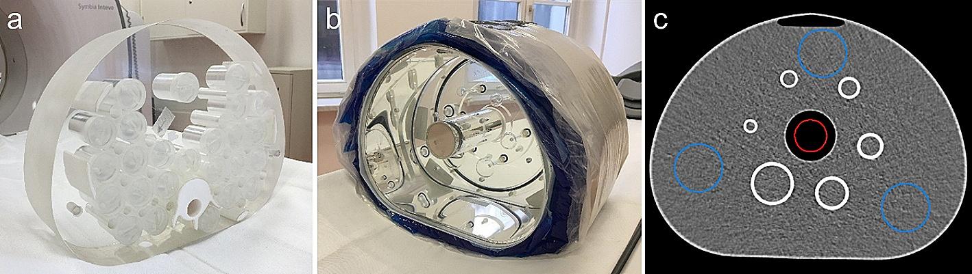
Image acquisitionThe experimental setup we used for image acquisition is composed of a Timepix3 application-specific integrated circuit (ASIC) bump bonded to a 0.5 mm thick Silicon sensor (MinipixEDU camera produced by Advacam) with a sensitive area of \(14.08\times 14.08\) mm\(^2\) coupled to a rank 31 no-two-holes-touching (NTHT) MURA Mask having 0.08 mm diameter holes in a 0.11 mm thick Tungsten sheet. The basic MURA pattern was duplicated in a \(2\times 2\) arrangement leading to a total mask size of \(9.92\times 9.92\) mm\(^2\). This coded aperture collimator used for the compact gamma camera MediPROBE2 was found to provide the highest lateral resolution among the intraoperative gamma cameras currently available [1]. We designed a 3D-printed case to keep the detector and the collimator in a fixed distance and axially aligned. The case holds the mask in a detector-to-mask distance b of 20 mm. We used an automatic linear axis, which enabled us to move the source automatically and with high precision without interrupting the measurement procedure. An L-shaped holder was attached to the axis on which the \(^\text \)Am source was clamped. The source’s nominal diameter is 1 mm but was previously measured to have a FWHM of 0.65 mm [17] and emits gamma photons of 59.5 keV. The source holder together with the gamma camera is depicted in Fig. 2. The coded aperture mask was originally designed for sources of 30 keV; nevertheless, the source-mask combination used in this paper was the only one available to us. Besides, it has been shown that usage of this mask at higher energies (80 kV X-ray beam) may reduce the image contrast but does not impede the imaging with a high CNR [18].
The images were recorded with a software tool from Advacam called Pixet. Instead of collecting a predefined number of photons per measurement, we kept the acquisition time constant for each acquisition. We recorded 9000 frames with an acquisition time of 0.1 s in “Tracking” mode. In this acquisition mode, the energy deposited by the interacting particles in the sensor is registered in each pixel, together with the time instant at which the interaction is revealed in the pixel. This information allows for the reconstruction of tracks released in the sensor from the impinging radiation, via a clustering algorithm based on time correspondence and spatial proximity of hits. This process, from which the name of the acquisition mode is derived, ultimately allows us to infer the type of radiation revealed by the detector based on its energy and the shape of its track. The time interval of 0.1 s per frame was chosen to avoid double counting of photons in a single pixel. A lower threshold of 5 keV was selected and no further energy windowing was applied (i.e. no hit was discarded from the final detector image based on the energy deposited in a pixel). Each acquisition lasted about 20 minutes, including 15 minutes active acquisition and time required for the intermediate processing of the detector. The pixel value in the resulting image represents the energy deposited in keV in each pixel integrated over the duration of the whole acquisition. We captured images at 21 different source-to-mask distances in the range of 12–20 mm in steps of 2 mm and from 20 to 100 mm in 5 mm steps (Fig. 2).
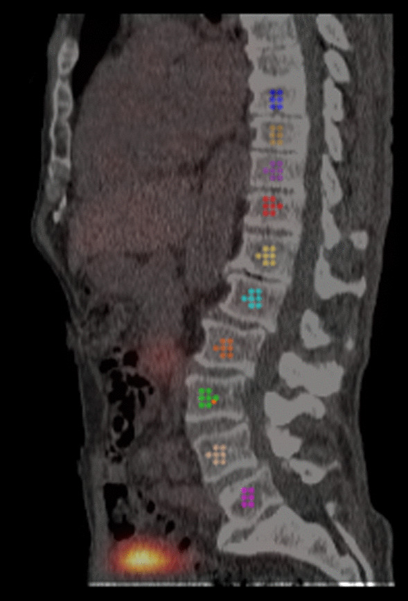
To eliminate outliers and cope with erroneous pixels, the raw detector images were preprocessed before undergoing image reconstruction. Preprocessing contains outlier replacement by the median value of their \(3\times 3\) neighborhood. Per image, all pixels having values outside the range of the 1st and 99th percentile were considered to be outliers. Additionally, Gaussian smoothing with a sigma of 1 pixel was applied. Figure 3b visualizes the raw and preprocessed data. The 21 acquired detector images and their preprocessed versions are available at https://zenodo.org/doi/10.5281/zenodo.8315861.
Fig. 2
Images were captured with source-to-mask distances from 12 to 20 mm in 2 mm steps and from 25 to 100 mm in 5 mm steps (21 positions). The photograph in the top right corner shows the source holder on the left and the gamma camera in its housing with parts of the Tungsten mask visible on the right
Reconstruction methodsWe analyzed two different reconstruction methods for CAI: the most commonly used MURA Decoding and an improved version of 3D-MLEM.
MURA decodingThe algorithm for MURA Decoding was already proposed with the invention of the uniformly redundant arrays (URA) [7], the predecessor of today’s widely used coded aperture pattern called Modified Uniformly Redundant Arrays (MURA) [19]. MURA Decoding is the inverse filter to the encoding pattern and is based on a linear and deterministic imaging model. The decoding pattern can directly be derived from the MURA pattern and its derivation from the encoding pattern can be found in [20]. The decoding pattern \(d_z(x, y)\) used in the reconstruction step is magnified to target an in-focus plane according to the distance between the plane and the mask, denoted as z [21]. MURA Decoding makes use of circular convolution which is assured by two aspects: the \(2\times 2\) arrangement of the basic MURA pattern, and the use of the central part of the detector image p(x, y). The central part, \(\textbf\left( p(x, y), z\right)\), is the portion of the detector onto which one entire mask pattern (i.e. a quarter of the \(2\times 2\) arrangement) is projected. The size of this projection surely depends on the magnification factor M given by Eq. (1), therefore on z. As a result, the size—in pixels—of the reconstructed images depends on the source-to-mask distance. The reconstructed image \(\hat_(x, y)\) is obtained by the following operation where “\(\circledast\)” denotes the circular 2D convolution operator:
$$\begin \hat_(x, y) = \textbf\left( p(x, y), z\right) \circledast d_z(x, y). \end$$
(2)
MURA Decoding can be considered the most widely used reconstruction method in CAI, due to its simplicity and speed when carried out in the Fourier domain [22]. A limitation of MURA Decoding is the underlying linear and deterministic imaging model. Especially when imaging sources of low photon flux, degradation due to substantial Poisson noise contribution must be expected. Deviations from the linearity assumption are known and the induced systematic noise increases as the source moves closer to the camera [10, 23]. The algorithm used in this paper has been implemented in MATLAB R2022b and to accelerate the process, the convolution is carried out in the Fourier domain. The pixel values of the reconstructed images are of minor importance for this study and only the relative values affect the CNR and hence the axial resolution.
3D-MLEMFig. 3
a Successive number of iterations for the 3D-MLEM algorithm applied to the source and reconstructed at 30 mm. b Raw (left) and preprocessed detector image (right). c The left image shows the forward projection of 3D-MLEM for the source at 40 mm and the right image shows the reconstruction at 40 mm. Due to the \(2\times 2\) arrangement of the basic MURA pattern, multiple ghost sources (blue arrows) along the image border emerge in addition to the true source (green circle) from the 3D-MLEM algorithm for sources that are more than 40 mm away
The maximum likelihood expectation maximization algorithm (MLEM) is an iterative algorithm that estimates the source distribution with the highest likelihood assuming the measured detected photons follow a random Poisson process [24]. The original MLEM algorithm was adapted to CAI by replacing the computationally expensive system matrix with a convolutional approach [10]. For more information, the reader is referred to [22]. Additionally to the 2D reconstruction method, Mu et al. [10] extended this algorithm to differentiate between different source-to-mask distances. Thus, an entire 3D source distribution can be reconstructed. Similarly to MURA Decoding, the entire gamma camera is solely defined by its point-spread function (PSF) \(h_z(x, y)\). The algorithm for the \((\text +1)}\) iteration of reconstructing the source distribution \(\hat_^+1)}(x, y)\) at a source-to-mask distance z is given by
$$\begin \hat^+1)}_z = \frac^)}_z}^ h_z} \cdot \left[ h_z \times \frac^ \hat^)}_ *h_ }_z^)} *h_z } \right] \end$$
(3)
where “\(*\)” represents the linear 2D convolution, “\(\times\)” the 2D correlation and “·” the point-wise multiplication. For better readability the lateral coordinates (x, y) have been omitted.
However, two aspects are not taken into account by 3D-MLEM: first, a mask that is smaller in dimension than the detector and second, transmission of gamma photons through the radiopaque material. As these two conditions were verified in our experimental setup, we extended the 3D-MLEM algorithm with two modifications: a more general normalization term \(n_z\) that accounts for the size difference between the mask and the detector and a forward simulation function \(\textbf\), which incorporates mask transmission.
Normalization term The 3D-MLEM formula is derived from the general MLEM formula with the system matrix \(}\), where its entries \(a_\) denote the probability that photons from source j are detected in detector pixel i. In literature the following normalization term, also referred to as sensitivity, can be found [24]:
$$\begin n_j = \displaystyle \sum _^ }_ \end$$
(4)
This summation over the matrix columns represent the summed likelihood that the photon from source j is detected by any pixel of the detector. \(n_j\) is a function over j and in general, this is not a homogeneous distribution. When the coded aperture mask is smaller than the detector, photons that are emitted further outside the center have a higher possibility to pass through a pinhole but not hitting the detector. One can imagine this by looking at the mask shadow cast by an off-center point source, where only part of the shadow hits the detector. The further off-center the source is, the higher the share of the shadow that is not falling within the detector area and the smaller the summed likelihood \(n_j\) becomes. The normalization factor \(n_\) ensures that the inherent forward projection has approximately as many detected photons as the given detector image p.
Translated to the convolution-based 3D-MLEM algorithm the normalization factor \(n_j\) is an image that depends on the source-to-mask distance \(n_z\). It can be calculated offline by a backward projection of an entirely illuminated detector to the plane in focus. Thus, we obtain \(n_z\) by calculating the cross-correlation between an all 1 image (\(\textbf\)) and the PSF at the given distance z:
$$\begin n_z = h_z \times \textbf \end$$
(5)
Forward simulation with transmission Transmission noise emerges from photons that penetrate the mask and in this paper it is approximated as uniform background noise proportional to the transmission coefficient of the coded aperture mask. With a mask thickness of 0.11 mm and a 59.5 keV source (see “Image acquisition” section) the transmission probability t of our setup is approximately 46%, meaning that about half of the photons pass through the mask. Because this transmission is high, the forward projection \(\textbf\) of the 3D-MLEM algorithm had to be adapted. The projected image becomes a weighted superposition of the projection of the reconstruction \(f_z\) and a uniform transmission noise image. The weight is set according to the transmission rate t and the sum of emitted photons from the in-focus plane \(f_z\):
$$\begin \textbf\left( f_z, h_z\right) = (1-t) \left( f_z *h_z \right) + t\, \sum _ f_z . \end$$
(6)
Additionally, we do not use the PSF of the NTHT pattern but of the two-holes-touching (THT) pattern to avoid periodical background noise [22].
In contrast to MURA Decoding, we decided to use the entire detector image for the reconstruction. This choice ensures that the output maintains a consistent size of \(256\times 256\) pixels. Because MLEM is based on the convolutional model, the field of view (FOV) is equal to the FOV of a single pinhole collimator. All in all, the proposed 3D-MLEM algorithm can be summarized as follows:
$$\begin \hat^+1)}_z = \frac^)}_z} \cdot \left[ h_z \times \frac^ \textbf\left( \hat^)}_, h_\right) }\left( \hat_z^)} *h_z \right) } \right] . \end$$
(7)
The 3D-MLEM algorithm assumes that the pixel intensity represents photon hits. Our detector images, however, represent deposited energy per pixel. The conversion to photon hits is not trivial due to charge sharing between neighboring pixels. Comparing the axial resolution of the source at 50 mm based on the detector image and on the same image divided by 59.5 keV (ignoring any charge sharing), the absolute difference was less than 2.28 µm Thus, we decided to not use any conversion and directly apply the 3D-MLEM to our captured detector images. As with MURA Decoding, the pixel values of the reconstructed images do not affect the axial resolution and only the relative intensities will influence the CNR. We decided to apply 40 iterations for the reconstruction from the acquired detector images (see Fig. 3a) since, from visual inspections, we found that to be a good compromise between noise amplification and reconstruction quality. The 3D-MLEM algorithm was implemented in Python (3.8) using the NumPy (1.24) library and, similar to MURA Decoding, all convolutions are performed in the Fourier domain.
Assessing the axial resolutionThe axial resolution expresses how well a point-like source can be localized in the depth direction, i.e. along the z-axis. We use the profile of the contrast-to-noise ratio (CNR) along the z-direction to determine the axial resolution as the full width at half maximum (FWHM) of this Gaussian-like curve: this provides a more intuitive understanding of the spatial resolution and takes into account not just the source intensity—as in [3], where the pixel intensity of the source was used to compute the axial spatial resolution—but also how well the source can be distinguished from the background noise. The following definition of the CNR was employed:
$$\begin CNR = \frac - \bar}}\,, \end$$
(8)
where \(\bar\) denotes the mean intensity of the signal near the true source position, while \(\bar\) and \(\sigma _\) are respectively the mean intensity and the standard deviation of the background.
First, we reconstructed each source’s image within a broad range from 5 to 100 mm in 5 mm steps to locate the source. Second, we reconstructed images within a tighter z range containing the actual source position in 0.5 mm steps resulting in sets of images ranging from 60 to 240 images for MURA Decoding and 54 to 101 for 3D-MLEM. From here on, we will refer to a set of reconstructions of the same detector image at different depths as an image stack. For easier handling, the reconstructions from MURA Decoding were resized by bilinear interpolation to the image size of the reconstruction at the true source position. To quantify the impact of the resizing procedure, the axial resolution was computed for both the resized and non-resized stacks of reconstructions for a source placed at 30 mm. The resulting values were \(11.9 \pm 0.5\) mm for the resized and \(12.5 \pm 0.5\) mm for the non-resized one, which are compatible within the errors. Therefore, for the sake of simplicity, we decided to continue our analysis on the resized stacks. No resizing was required for 3D-MLEM images, as the algorithm returns images of a fixed size.
To determine the CNR for each image of a stack, the signal S and background B is required. To minimize the influence of the operator on the CNR computation, we wrote a semi-automatic algorithm that sampled the whole image, thus avoiding manually choosing regions of interest (ROIs) for S and B and ensuring the reproducibility of the procedure. The diameter of the ROI was chosen separately for each stack, i.e. each captured detector image, based on the true source size (see “Image acquisition” section) and the true source distance. First, the FWHM source diameter of 0.65 mm was converted to pixels with respect to the FOV at the true source distance and then it was rounded to the nearest integer number to obtain the ROI diameter. The equation for the FOV of MURA Decoding was taken from [3] and for 3D-MLEM the FOV of a pinhole collimator is used.
An imageJ macro sampled all possible positions of the ROIs per image stack: depending on the image size and ROI diameter there were between approximately 14,000 and 31,000, and 54,000 and 65, 000 ROI positions per image for MURA Decoding and 3D-MLEM. For each ROI its position in pixels, the average intensity, and standard deviation were calculated and stored for each image of the stack. The ROI with the highest average intensity in the in-focus image (i.e. the image reconstructed at the z where the source was actually located) was selected as the signal S. A constraint was introduced that restricted the signal ROI to be in the inner 50% of the image area to avoid measuring one of the ghost sources along the image border as visible in Fig. 3c. Furthermore, ROIs that overlapped with S were discarded from further processing. All other ROIs were selected as background ROIs and the background mean \(\bar\) was computed as the average intensity of all background ROIs; the same was performed for the standard deviation: \(\bar\). Once the signal ROI was found in the in-focus image its position was kept the same for each image of the stack. The same was done for the ROIs where \(\bar\) and \(\bar\) were computed.
Finally, a Gaussian curve with offset of the following form was fitted through the CNR profile: \(\text (z) = \alpha +(\beta -\alpha )\,\exp \left( -(z - \gamma )^2 / (2 \, \delta ^2)\right)\) with the fitting parameters \(\alpha\), \(\beta\), \(\gamma\), and \(\delta\). The fitting procedure was carried out in Python (3.8) with the curve_fit function from SciPy (1.10). The axial resolution and its standard deviation through the fitting procedure are reported as FWHM with following correspondence between the Gaussian’s standard deviation \(\delta\) and the FWHM [13]:
$$\begin \text = 2\sqrt} \,\,\delta \approx 2.35 \,\, \delta \end$$
(9)
Assessing the lateral resolutionIn order to compare our results with values from literature we measured the lateral resolution as well. This allows us to additionally report the axial resolution relative to the lateral resolution. Following the suggestion given in a recent review on intraoperative gamma cameras [1], we determined the lateral resolution for 30 mm, 50 mm, and 100 mm source-to-mask distance.
To compute the lateral resolution, we first selected the in-focus image within the image stack used for the assessment of the axial resolution. We then took the source profile along the row with the highest pixel intensity. A Gaussian curve with offset was fitted to this profile and the FWHM value was obtained from the resulting standard deviation. As the FWHM value was given in pixels, it was converted to mm by using the FOV of the respective reconstruction method.
留言 (0)