The vestibulospinal (VS) neurons of the brainstem vestibular nuclei provide the sensory signals defining the instantaneous status of the head in space to the spinal motor circuits that control reflex head/neck and limb movements and posture. The head in space might be stationary, either in its normal posture, rotated on the neck or tilted with respect to the orientation of gravity, or moving, either during voluntary activity or involuntarily, as the result of external perturbations. The key sensory signals driving the reflex action originate from hair cells in the inner ear vestibular structures: the otolith organs, namely the utricle and the saccule, that sense the sum of inertial acceleration and orientation of the head with respect to gravity and the three orthogonally arranged semicircular canals that transduce angular head rotation [reviewed by Wilson and Melvill Jones (1)]. These continuous vestibular inputs are combined with motion cues derived from neck proprioceptors and other modalities onto the VS neurons. This central representation of the head and body in space drives the rapid reflex adjustments necessary to maintain the animal’s equilibrium and stability. These sensory-to-motor signals carried in the VS pathways interact on their spinal target neurons with involuntary motor-to-sensory signals arising from the effectors, like the position and movement of the head and neck on the trunk, and purposeful voluntary commands from cognitive centers to enable the appropriate behavioral response(s) (2). At the same time, the VS neurons provide a continuous excitatory drive, called “tonus labyrinth” (3), to the spinal motor circuits to hasten their reactive responses to external perturbations. The tonic excitation raises the resting voltage level of the neuron so that new synaptic currents imparted by descending inputs, such as from VS terminals, readily bring the neuron closer to the discharge threshold (4).
The principal VS pathways are (1) the medial vestibulospinal tract (MVST) that descends in the medial longitudinal fasciculi (MLF) and ventromedial funiculi either ipsi- or contralaterally with respect to their vestibular (8th cranial) afferent nerve input and innervates spinal neurons located mainly in the ventral horn throughout the cervical segments (5); and (2) the lateral vestibulospinal tract (LVST) that course ipsilaterally with respect to their 8th nerve input in the lateral to ventrolateral funiculi and are distinguished by two divisions: (i) a cervical-projecting tract that can target the upper cervical segments or the lower cervical segments that contributes to reflex control of shoulder and forelimb (arm) muscles or both; and (ii) a lumbosacral-projecting tract that provides a rapid synaptic drive to maintain stable posture and reflex control of the lower body.
When our head is perturbed, say for example during locomotion, signals arising in the vestibular hair cells and neck proprioceptors are generated to produce the vestibulocollic reflex (VCR) to provide head stability in space, the vestibulo-ocular reflex (VOR) to hold images of stationary objects steady on the retina (6, 7), and to a lesser extent the stretch reflex-like cervicoocular reflex (5, 8). The VCR interconnects the vestibular-nerve afferents supplying the sensory hair cells, the secondary MVST and cervical-projecting LVST neurons, and the cervical motoneurons (5, 9, 10). Another possible link of the VCR is made by vestibuloocular collic (VOC) neurons, which have dual destinations: one to the cervical spinal cord via the descending MLF, like contralateral-projecting MVST axons, and the other to the contralateral oculomotor nuclei via the ascending MLF (11–14). In addition to direct VCR pathways, there are indirect vestibulo-reticulo-spinal pathways (10). At the same time, when the head is moved by either a perturbation or voluntarily, other cervical-projecting LVST neurons are activated, influencing alpha and gamma motoneurons to forelimb muscles (15, 16).
Evolution of the bony skull from the early hominids to present humans, as revealed by the fossil evidence, brought about a progressive movement of its center of gravity in the mid-sagittal plane (X–Z plane) to slightly in front of the occipital condyles (viz. the fulcrum), thereby reducing the jaw and neck muscular masses but more importantly benefiting the stability of the head and neck (17, 18). The heads of extant mammals, and most notably those of subhuman primates, are still relatively massive and are positioned above a multilinked (typically seven) cervical spine, the most complicated articular system of the body, and behave as an unstable inverted pendulum on top of a highly mobile neck under most conditions. The range of mobility at the different cervical joints, such as the skull to C1, C1 and C2, C2 to C3, and C3 to C7, varies. The movements of flexion and extension, lateral bending from the midline, and axial rotation from the midline of the head and neck are not entirely confined to single loci but distributed along the cervical axis (19–23). The distribution of synaptic fields of VS axons from specific and confined segments to a more uniform innervation along the cervical segments likely corresponds to the mechanical structure and constraints of the evolved primate head and neck. The importance of the VS pathways to vertebrate survival is reflected in its early development and myelination (24–29), and the hodologically defined vestibular populations conserved from early vertebrate evolution in distinct and mixed neuroepithelial segments: projections to the VOR circuit originate from neurons in the rostral to middle rhombomeres and the origins of the ipsi- and contralaterally projecting VS pathways are found in the middle to the more caudal rhombomeres (30–32). The behavioral and functional manifestations of early vestibular maturation can be seen when a foal almost immediately after birth rights itself in direct opposition to the force of gravity and starts to correct body sway. Lambert et al. (33) demonstrated in mice that the vestibular-mediated drive to the cervical motoneurons continues rapidly in the first weeks postnatal. These striking demands on motor performance are possible due to the established sensory signals from the otolith and canal hair cells delivered by the VS system to the relevant motor effectors (34, 35). It is reasonable to postulate that the ontogeny of motor behaviors associated with the VS system reflects survival pressures among the vertebrate species.
Goldberg and Fernández published their landmark investigations of functional properties of semicircular canal afferents in 1971 (36–38) and established the squirrel monkey as a valuable experimental model of vestibular structure and function. The binocular visual field of the squirrel monkey (about 146°) and human (about 140°) are comparable (39), making the squirrel monkey a model widely used in vision research (40). The average squirrel monkey is a small primate (~800 g), having a relatively high brain weight to body weight ratio (approx. 1:25 versus the human’s 1:50). Its encephalization quotient, the ratio of brain mass to body mass, of 2.8 places it the fourth highest among those of the fifty primate species studied by Jerison (41), and has proven to be a valuable model in clinical neuroscience (42, 43).
This study aimed to provide a structural foundation for subsequent functional studies in alert and behaviorally trained squirrel monkeys to specify the role of the VS pathways in neck-eye coordination in relation to gaze. The significance of head stabilization is seen in our ability to change gaze orientation, maintain binocular fixation during most activities, detect self-motion, and adaptively react to externally imposed head/body perturbations. Despite the importance, wide gaps remain in our understanding of basic VS mechanisms. The present study provides a descriptive analysis of the anatomical organization of identified secondary MVST neurons, VOC neurons, and cervical-projecting LVST neurons in the squirrel monkey. We used intracellular recording, dye labeling, and orthodromic and antidromic stimulation protocols to map and compare the projections and terminations of VS neurons in the brainstem and cervical spinal segments. The primary advantage of the squirrel monkey in this experiment is the relatively shorter length between its cervical segments (~2–3 mm) compared to that of the cat (5–12 mm, personal observations), thereby permitting the visualization of labeled axons, their branching patterns, and terminal synaptic fields within the brainstem and over a greater number of spinal segments. These techniques were also used to identify selected targets, such as central cervical nucleus neurons, sternocleidomastoid, trapezius, and splenius motoneurons, and map their connection to the VS pathways. The results in the primate support the seminal work done by Shinoda and his team in the cat (44–48), particularly the VS trajectories and branching distributions in the cervical spinal cord. The major findings of the study also extend those studies by including, where possible, VS synaptic projections to brainstem neuron pools, complete mapping of individual VS axons in the cervical segments, 8th nerve synaptic input(s) to likely targets of specific spinal neuronal populations, and the likely matching of VS innervation to the skeletomuscular organization of cervical spinal cord. Several review articles have partially described the findings (5, 9, 49, 50).
Materials and methods Surgical preparationAll surgical and experimental procedures were conducted according to the National Institutes of Health Guide for the Care and Use of Laboratory Animals, 8th edition, and approved by the Institutional Animal Care and Use Committee at Oregon Health & Science University (OHSU), Portland, OR. All experimental procedures and tissue processing were conducted at OHSU.
Experiments were performed on adult male squirrel monkeys, Saimiri sciureus (NCBI: txid9521), weighing ~0.8–1 kg. All animals were initially anesthetized with an intramuscular injection of ketamine (40 mg/kg) and acepromazine maleate (1 mg/kg). A femoral vein was cannulated, and a continuous intravenous infusion of 11 mL lactated Ringer solution, 5–10 mg sodium pentobarbital, and 0.2 mg dexamethasone per hour was maintained. Systemic arterial pressure was continuously monitored using an indwelling catheter in the femoral artery, which was placed in series with a pressure transducer. Rectal temperature was kept near 38°C by a heating pad and radiant lamp. After surgical preparation, including tracheal intubation, the animal was immobilized with pancuronium bromide (100 μg/h) and ventilated with room air; end-tidal PCO2 was monitored and kept near 4%. A bilateral pneumothorax was done to reduce respiratory pulsations of the spinal cord to facilitate intracellular recordings; atelectasis was controlled by routine hyperinflation of the lungs.
Neural recording and stainingIntracellular recordings were made from axons between C1 and C3 with glass micropipettes filled with 3–4% biocytin (Molecular Probes; Cat# B-1592) or 2.5% neurobiotin (Vector Labs; Cat# SP-1120) in 2 M NaCl, 0.05 M KCl, and 0.1 M Tris buffer (pH 7.4; R = 30–50 MΩ). After sufficient axon injections were completed, intracellular recordings were then made from cell bodies of cervical spinal neurons with glass micropipettes filled with 2–4% biocytin dissolved in 0.5 M KCl and 0.05 M Tris buffer or 2.5% neurobiotin in 1 M potassium methyl sulfate (CH3KO4S) and 0.05 M Tris buffer (pH 7.36). In several pilot experiments conducted at the end of a separate study (51), the somas of selected VS neurons, identified by their monosynaptic input from the 8th nerve and antidromic activation from pulses applied to an electrode array at C1 but not at C6, were labeled with biocytin as described above; the data from these experiments were unreported and served as a prelude to the present study. Examples are given in Figures 1A,B of a VOC neuron, in Figure 2 of two cMVST neurons, and in Figure 3 of two LVST neurons. Since the primary focus of the study was to describe the synaptic organization of VS axons in the cervical spinal cord, stimulating electrodes were not implanted at C1 unless specifically stated because the integrity of the cervical segment at the electrode site was potentially compromised.
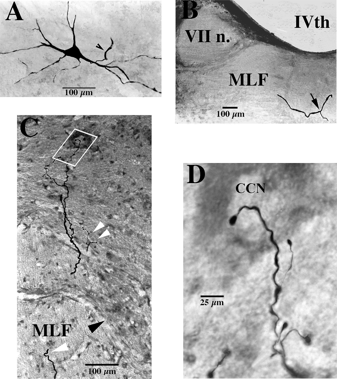
Figure 1. Soma, axon bifurcation, and terminal synaptic morphology of two VOC neurons. (A,B) Photomicrographs show the labeled soma of a VOC cell and the initial segment of its axon (arrowhead) recovered in the ventral Lateral Vestibular Nucleus in panel (A) and its axon bifurcation (arrow) in the contralateral MLF rostral to its soma in panel (B). (C,D) A separate VOC neuron is shown penetrating the ventral horn of lamina VII dorsal to the medial wall of lamina VIII (indicated by the black arrowhead). The axon branches targeted cell groups in lamina VII (double white arrowheads) and a neuron (white box) in the central cervical nucleus (CCN) in panel (C). The presumed targeted CCN neuron (located immediately dorsal to the labeled processes in this image; 60 μm horizontal section) is shown in the enlargement along with the terminal processes of the VOC collaterals in panel (D). The neuron received short-latency, ~2 ms, disynaptic excitatory post-synaptic potentials from shocks applied to the contralateral vestibular nerve (Vc) that summated into action potentials. See Methods and Results for more details. Calibration bars are given in each panel.
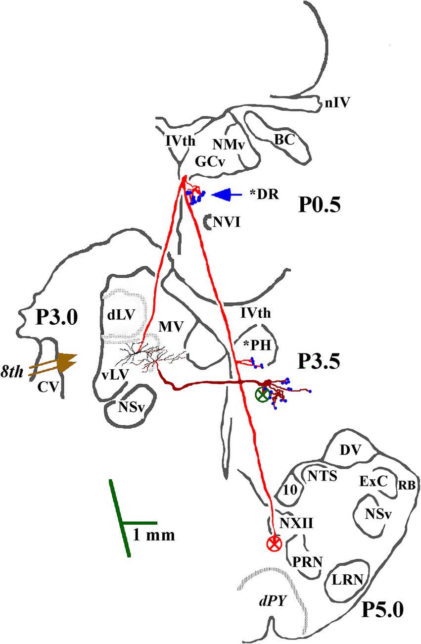
Figure 2. Soma location and initial axon trajectory and branching in the caudal brainstem of two cMVST neurons. Neurons were intrasomatically recorded and labeled to show their axon trajectories and innervation within the caudal brainstem, although limited. The axon of the more lateral neuron (in red) projected rostrally from its soma. It crossed into the contralateral MLF, like VOC neurons, but without bifurcating into ascending and descending branches, issued synaptic specializations in the dorsal Raphe (*DR), reversed course and projected caudally in the descending MLF with a minor input to the prepositus hypoglossal (*PH) nucleus. The other cMVST neuron projected across the midline into the descending MLF and issued collateral input to the PH nucleus. Abbreviations are given in Methods.
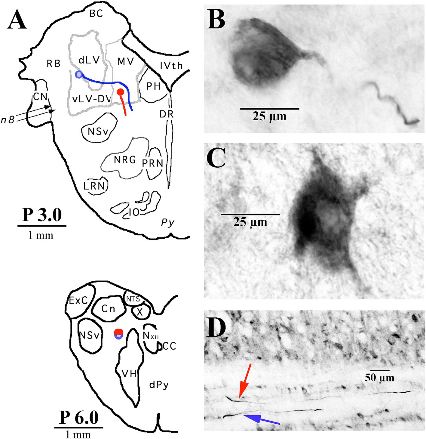
Figure 3. Two examples of LVST soma locations in the vestibular nuclei and their initial axon trajectories in the brainstem. (A) Soma labeled in blue was located in the ventral lateral vestibular nucleus (vLV) and is shown in the photomicrograph in panel (B), and the other neuron labeled in red was located in the ventral portion of the medial vestibular (MV) nucleus and is shown in the photomicrograph in panel (C). The lower panel (A) gives a schematic representation in the transverse plane of the two axons, traveling in tandem at P 6.0 in the caudal brainstem. (D) Photomicrograph of the two axons in the sagittal plane at P 6.0 coursing in a fiber track below the cuneate nucleus (Cn). Both neurons were intra-somatically labeled and antidromically activated from pulses applied at C1. Axons could not be followed into the spinal sections. Abbreviations are given in Methods.
For both axon and soma recordings, DC- and AC-coupled records were conventionally preamplified, filtered below the Nyquist frequency, and externally amplified to span the 12-bit range of the data acquisition device (1401Plus, Cambridge Electronic Design (CED), Cambridge, England) interfaced to a 80×86 computer. The cell’s AC- and DC-coupled voltages were sampled at 20 kHz and 3.5 kHz, respectively, in the acquisition software (Spike2, CED). In all cases, electrical pulses consisted of 100-μs constant-current shocks delivered via a stimulus isolation unit at 1–2/s as a single stimulus, as 3–5 pulses in a train, or in brief cathodal or anodal polarization of the 8th nerve electrodes and time stamped events. Data were transferred to a Macintosh platform and visualized later using scripts written for the Igor (WaveMetrics, Lake Oswego, OR, USA) package.
Impaled axons and cells initially had resting potentials of −50 to −70 mV. To stain the individual neurons with biocytin or neurobiotin, negative current was passed through the electrode to hyperpolarize the cell from −2 to −5 mV and positive current pulses of 8–25 nA, 1/s, 70% duty cycle were applied. During the injection phase, the membrane potential was monitored during the off-cycle, and the injection was periodically stopped to inspect the evoked potentials. An injection was stopped if the resting potential rose more positive than −20 mV. Only one injection, or attempted injection, of a cell was made in an individual electrode track, and the electrode was immediately withdrawn from the tissue. A minimum distance of 1 mm was kept between injection sites, and axons were sought on both sides of the spinal cord. No attempt was made to first extracellularly record spontaneous or induced discharges before penetrating the axon. This can give potentially false results. Based on the cell’s responses to applied stimuli from multiple sites, it was repeatedly observed that an axon extracellularly recorded first was not the same as that immediately penetrated, although one or more responses could have comparable latencies. Therefore, all identification and labeling procedures were done only under intracellular conditions.
Electrophysiological identification of 8th nerve inputUsing a retroauricular approach to expose the middle ear on both sides, one insulated Ag/AgCl2 silver wire (250 μm dia.) bared for 1 mm at its tip (cathode) was inserted into the perilymphatic space of the vestibule through a hole bored in the promontory between the round and oval windows to electrically excite fibers in both the superior and inferior divisions of the 8th nerve; a bared coiled Ag/AgCl2 silver wire (anode) was placed rostrally in contact with the bone. Vestibular neurons were identified by their synaptic responses to bipolar pulses applied to the wires on the ipsilateral (Vi) or contralateral (Vc) 8th nerves (Figure 4). Secondary cervical-projecting vestibular neurons were selected for study based on two criteria: (1) the cell’s latent period of orthodromic response to electrical stimulation of the 8th nerve did not exceed 1.6 to 2.0 ms from C1 to C3, indicating a monosynaptic connection to the vestibular nerve afferents, and (2) the cell was not antidromically activated from the T6-10 stimulation site.
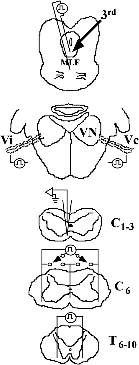
Figure 4. Methods to identify VS neurons in the squirrel monkey. Cartoons show the placement of stimulating electrodes: (1) in the rostral medial longitudinal fasciculus (MLF) at the caudal pole of the oculomotor (IIIrd) nuclei to identify a possible rostral ascending branch from a bifurcating axon, such as the vestibuloocular collic (VOC) neuron, (2) in the middle ear space to orthodromically excite ipsi- (Vi) and contralateral (Vc) 8th nerve afferents that project to the vestibular nuclei (VN), (3) in the ventrolateral funiculi of both sides and the centerline of the spinal cord at C6 to antidromically activate the descending axons that terminate in the lower cervical segments or pass more caudally, and (4) in the ventrolateral funiculi of both sides of the spinal cord at T6-10 to antidromically activate the descending axons of neurons that project to the lumbosacral spinal segments. Intra-axon and -soma recordings and dye labeling were made on either the left or right side and spaced at 1 mm intervals at C1-3.
Electrophysiological identification of cervical-projecting vestibular neuronsFigure 4 shows a schematic representation of the recording and stimulation techniques. Dorsal laminectomies were made to expose the spinal segments of C1–C8 and T6-10. Single axons and neurons were recorded between C1-3 on either the left or right side, and dye injections were spaced at 1 mm intervals and mapped to an individual drawing with landmarks. Dye spots were made at the end of the experiment to mark each cervical dorsal root entry bilaterally. The actual laterality of the recorded axon or neuron was verified by the dye spots, the specific mappings, and principally by histologically examining 60 μm horizontal serial sections.
At C6, an electrode array of 3 Ag/AgCl wires (200 μm dia.), insulated to within 1 mm of their tips, was placed in the ventrolateral funiculi on both sides, and the center wire was inserted along the midline to a depth beneath the central gray matter. Bipolar pulses were applied to combinations of the wires to estimate laterality for those axons projecting to that level of the spinal cord. Between T6-10, two stimulating wires were inserted into the ventrolateral funiculi on either side to activate lumbosacral-projecting axons. Antidromic spikes were recognized by their constant latent periods for near-threshold shocks and by their collision with orthodromic action potentials evoked by 8th nerve stimulation or spikes evoked by intracellular depolarizing currents.
Electrophysiological identification of ascending projection to the oculomotor nucleiTo identify the existence of a vestibular neuron having a bifurcating axon with both an ascending and a descending projection, a low-impedance glass microelectrode was lowered into the brain based on 3-D stereotaxic coordinates to target the rostral MLF between the IIIrd and IVth cranial nuclei (approximately A3.0; (52)). The optimal placement was guided by recording the field potentials evoked by Vi and Vc stimulation. The recording electrode was then replaced by a pair of insulated tungsten wires, separated from one another by ~3 mm and each bared for 1 mm (Figure 4); their placement was confirmed by recording comparable 8th nerve evoked field potentials with the stimulating electrodes. The location of the MLF electrodes was later confirmed in histological sections in each animal.
Electrophysiological identification of spinal neuronsMotoneurons supplying the splenius capitis (SPL) and sternocleidomastoideus (SCM) muscles on both sides were identified by their antidromic response to electrical stimulation of their peripheral branches at C2–C3. Flexible bipolar stimulating cuffs were routinely implanted on one or more branches of each muscle. The SPL insertion to the occiput was left intact but detached from the spinous apophyses; the SCM was left intact but retracted laterally to expose the nerve branches. In a few experiments, the C1 dorsal rami were also prepared for activating the suboccipital nerve supplying the rectus capitis posterior major and minor and the obliquus capitis superior and inferior; no neurons were identified from these sites in early experiments, and thus, this procedure was discontinued. Other likely targets of VS innervation, most notably central cervical nucleus (CCN) and cervical long propriospinal neurons were also sought based on spinal coordinates and T6-10 antidromic responses, respectively.
Histological proceduresThe animal was monitored and kept under anesthesia for 4–8 h after the last injection of an identified spinal neuron. This was done to provide more time for label diffusion within the VS axon and less time for the label transport to leave the soma of the spinal neuron. During that time, the laminectomy was extended to the thoracic stimulating array, and the dorsal root entry zones at each cervical and thoracic segment on both sides were marked by specific cuts and ink, and measurements of the distance from the obex to the spinal stimulating electrodes were taken. After the survival period, the animal was given heparin sodium (1,000 units, i.v.) and perfused transcardially, first with 1 L of 0.9% saline and then with 1 L of a fixative solution containing 4% paraformaldehyde and 0.2% picric acid in 0.1 M phosphate buffer (pH 7.4). The midpoints of each cervical and thoracic dorsal root entry zone were marked with dye and cuts, and the brain and spinal cord were removed and stored overnight in a solution of 30% sucrose in 0.1 M phosphate-buffered saline (PBS) at 4°C. Three blocks of tissue were routinely processed: precollicular midbrain to obex, obex to T1, and T2 to T6. Frozen 60-μm serial sections in the sagittal (brain) and horizontal (spinal cord) planes were collected in cold 0.1 M phosphate buffer, incubated in Vectastain (Elite ABC kit, 1:50 dilution; Vector Laboratories) with 0.2% Triton X-100 for >4 h, transferred to a solution containing 0.05% diaminobenzidine and nickel ammonium sulfate (0.6%) for >1 h, and reacted by the addition of 0.003% H2O2 in PBS. In the two pilot studies, VS neurons antidromically identified to project to C1 were intrasomatically labeled, and the brainstem and spinal tissue blocks were sectioned in the transverse plane and processed as described above; sectioning the tissue block, particularly the spinal segments, in the transverse plane critically limited the accurate reconstruction of the axon trajectory and collateralization. All sections were mounted on gelatin-coated glass slides, lightly counterstained with a modified methylene blue and basic fuchsin stain, and cover-slipped. Sections were examined using a Leitz microscope, and individually labeled axons were reconstructed using a drawing tube (camera lucida) at ×16 or ×25 magnification. Terminal and en passant boutons were examined under ×40 and ×100 oil objectives to estimate as precisely as possible their number within the terminal field for each branch. Digital images were captured with a Leica DC500 camera; common darkroom operations such as brightness and contrast were enhanced as needed in Adobe® Photoshop®.
Key to Abbreviations used in Figures: 10th (vagus) nucleus; 12, 12th (Hypoglossal) nucleus; BC, Brachium Conjunctivum; C, cervical; CC, Central Canal; CCN, Central Cervical Nucleus; CV, ventral cochlear nucleus; dLV, dorsal Lateral Vestibular nucleus (Deiters’); DM, dorsal motor neurons of lamina IX; dPY, decussation of the Pyramidal Tracts; DR, dorsal raphe nucleus; DV, Dorsal nucleus of the Vagus; ExC, External Cuneate nucleus; IO, Inferior Olive; IVth, IVth (Fourth) Ventricle; GCv, substantial grisea centralis, pars ventralis; LRN, Lateral Reticular Nucleus; MLF, Medial Longitudinal Fasciculus; MV, Medial Vestibular nucleus; NMv, mesencephalic nucleus of the Vth (trigeminal) nerve; NSv, spinal trigeminal nucleus; NTS, Nucleus of the Tractus Solitarius; NVI, VIth (Abducens) nucleus; NXII, 12th (hypoglossal) nucleus; RO; PH, Prepositus Hypoglossi nucleus; PRN, Paramedian Reticular Nucleus; RB, Restiform Body (inferior cerebellar peduncle); Roller’s Nucleus; nIV, nerve of the IVth (trochlear) nucleus; SA, Spinal Accessory (XIth) nucleus; T, thoracic; Vc, contralateral Vestibular (8th) nerve; Vi, ipsilateral Vestibular (8th) nerve; VII n., VIIth (Facial) nerve; VH, Ventral Horn; vLV, ventral Lateral Vestibular nucleus; VM, ventral motor neurons of lamina IX; VN, Vestibular Nuclei; VII, lamina VII (Rexed); VIII, lamina VIII (Rexed); X, lamina X (Rexed).
Results General classification of neuronsVestibulospinal (VS) were typed as ipsi- (i) or contralateral (c)-projecting MVST neurons based on their axon location in the descending MLF of the upper cervical spinal segments in relation to their monosynaptic input from the 8th nerve. For example, an iMVST and a cMVST cell were monosynaptically activated from the left 8th nerve, and their axons were located in the left or right MLF in the cervical segments, respectively. VOC neurons were comparably typed as cMVST cells but were, in addition, antidromically activated from electrical pulses applied to the rostral MLF between the IVth (trochlear) and IIIrd (oculomotor) nuclei, revealing a bifurcation of its axon in the brainstem. LVST neurons were monosynaptically activated from the 8th nerve, and their axons generally travel in the lateral funiculus as they enter the spinal cord at C1 and progressively migrate to the ventrolateral and ventral funiculi as they projected to the lower cervical segments.
General morphology of MVST and LVST neuronsFour examples of branching from the parent MVST axon in the ventromedial funiculus are shown in Figure 5. Typically, two or more collaterals were issued from an axonal branch off the parent axon before the processes reached the medial wall of the ventral horn of laminae VII and VIII (examples shown in Panels A [arrowheads] and B); less commonly observed the branches were issued immediately off the parent axon and did not collateralize until they entered the ventral horn (Panels C and D).
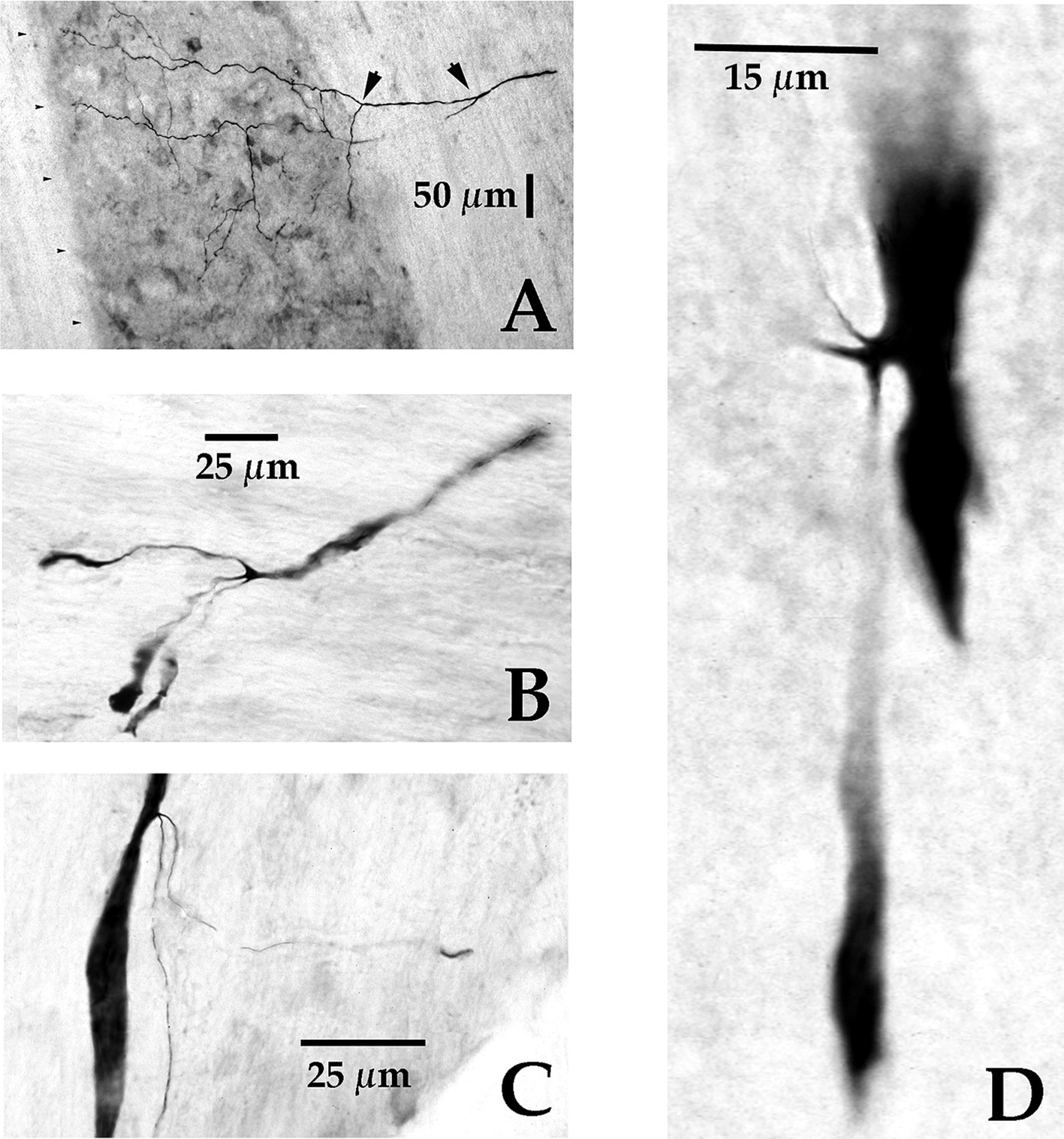
Figure 5. Axonal branching and collateralization of MVST neurons in the Cervical spinal cord. Photomicrographs show the typical branching features of two cMVST (A,D), one VOC (B), and one iMVST (C) axons projecting into the cervical spinal segments (taken from 60 μm horizontal sections). Calibration bars are given in each panel.
Three examples of branching from the parent LVST axon in the lateral funiculus at C1 are shown in Figures 6A–C. Typically, the first branches were issued near to or across the lateral wall of the ventral horn in lamina IX (Figures 6A,B); less commonly observed were collaterals issued from an axonal branch more distantly from the ventral horn (Figure 6C). All VS axons reported here were tested and found unresponsive to lower thoracic cord stimulation. Lumbosacral projecting LVST axons recorded and labeled in these experiments were reported in a separate study (53).
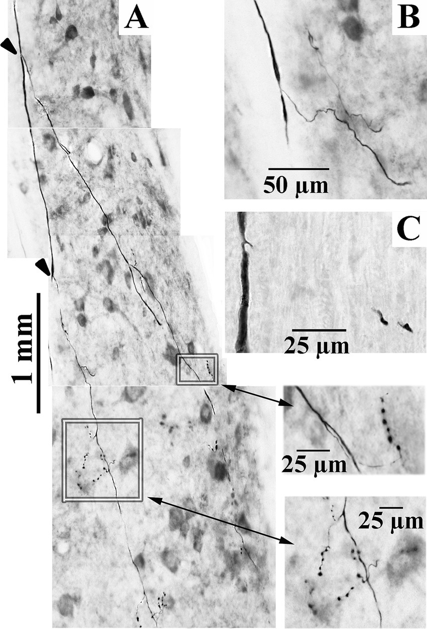
Figure 6. Axonal branching and collateralization of cervical-projecting LVST neurons. Photomicrographs show the typical branching features of three LVST axons innervating the cervical spinal cord (A–C). Two branches [indicated by arrowheads in panel (A)] were issued from the parent axon in the lateral funiculus. Synaptic specializations from collaterals of these branches are highlighted by boxes and enlarged in the corresponding inserts indicated by double-headed arrows (taken from 60 μm horizontal sections). Calibration bars are given in each panel.
Of the 134 axons identified by their short-latency, monosynaptic input from the 8th nerves, 35 (26%) were successfully labeled to permit a moderate to complete reconstruction of their projection patterns in the cervical spinal segments. Of the 35 axons, 9 (25.7%) were classified as cMVST, 8 (22.9%) as iMVST, 10 (28.6%) as LVST, and 8 (22.9%) as VOC axons. The orthodromic latency from the 8th nerve stimulation averaged 1.37 ms ± 0.31 (SD; n = 35). Eight (4 cMVST, two iMVST, and two VOC) axons of the 35 (22.9%) received an inhibitory input from the opposite 8th nerve, and two (cMVST) received an excitatory input from both 8th nerves. The latency of antidromic activation from the rostral MLF for the VOC axons averaged 0.91 ms (±0.22 ms SD).
Table 1 gives the number of axon (parent) branches and synaptic (en passant and terminal) specializations validated for each group of VS neurons at eight different sites from the obex to the first cervical dorsal root entry at C1 to the most distal segment C7 to C8. Since the axons were recorded and labeled in the upper cervical sections, the given observations in the upper segments for each VS population are necessarily more complete (see Methods for criteria inclusion). The results at C1–C2 show that the VS population’s innervation density is not uniform. Between C1–C2, VOC and LVST exhibited the largest number of branches from the parent axon (44 total with a mean of 5.5 ± 3.2 and 43 total with a mean of 3.6 ± 1.9, respectively) and the highest number of observed boutons (5,068 total with a mean of 115 ± 126.5 and 5,088 total with a mean of 118 ± 107, respectively). LVST neurons maintained their dense innervation of the ventral horn from the obex to C1 and at C2–C3. The cMVST preferentially targeted the two middle cervical segments from C2 to C4, and iMVST cells, which are presumed inhibitory on their targets (54), exhibited a more sparse innervation of the cervical ventral horn.
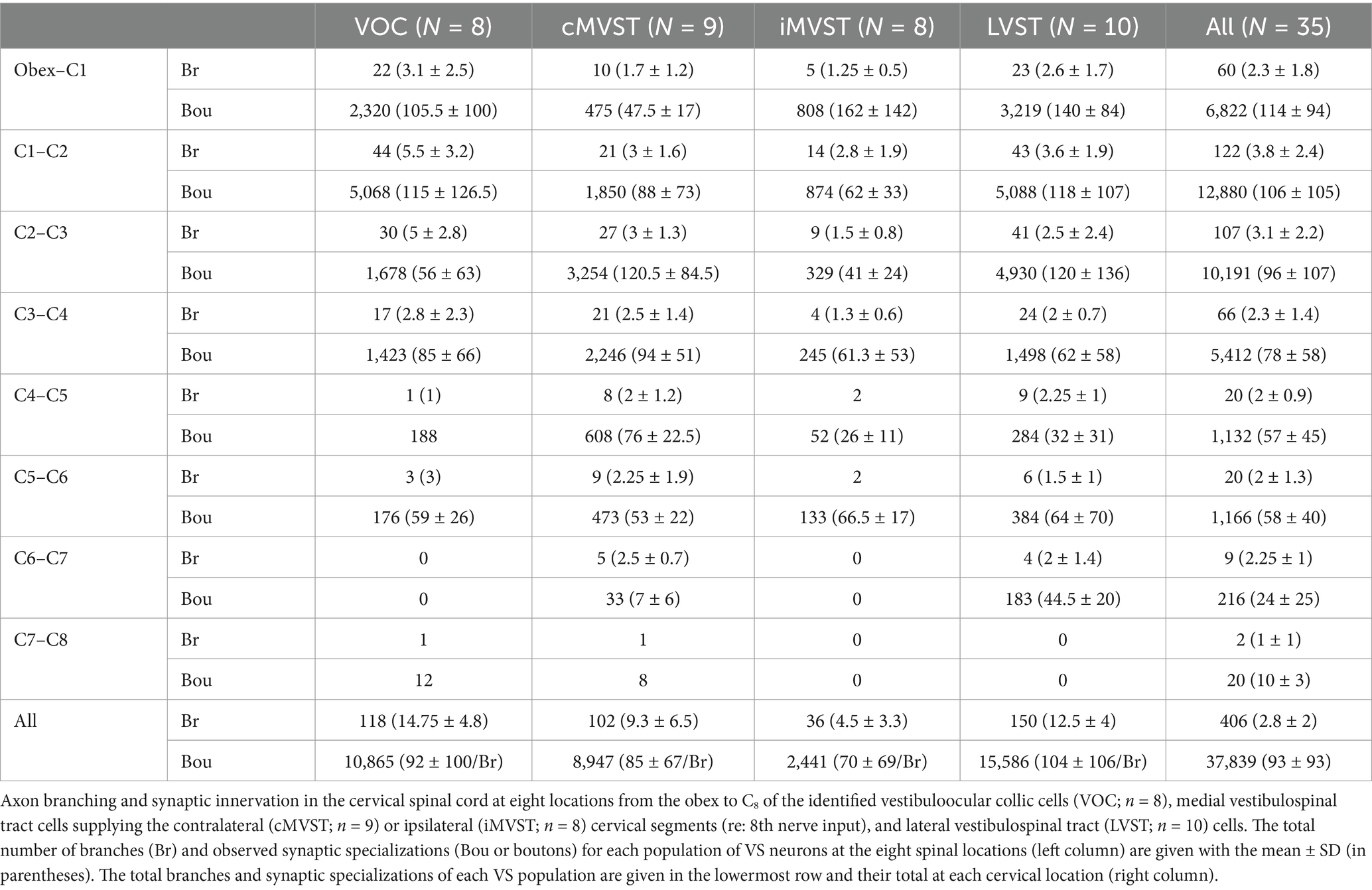
Table 1. Morphological properties of secondary VS neurons in the squirrel monkey.
Morphology of vestibuloocular collic (VOC) axonsVOC neurons exhibited the more prolific innervation to caudal brainstem nuclei of the sampled population of VS neurons. In addition, VOC axons had expansive innervation patterns in the ventral horn of the cervical segments, mainly in laminae VII and VIII and, to a lesser extent, lateral and ventromedial lamina IX, from C1 to C8. Figure 1 shows four photomicrographs of two labeled VOC neurons. The VOC neuron shown in A and B was labeled intra-somatically (described in Methods): the soma and its axon (arrowhead) in the left ventral lateral vestibular (vLV) nucleus is shown in A and the same cell’s bifurcating axon (arrow) in the contralateral (right) MLF beneath the IVth ventricle about 1.5 mm rostral to its soma in B. The more dorsal branch projected rostrally and was antidromically-activated from pulses applied to the MLF at the level of the caudal IIIrd nuclei; the thinner branch projected to the cervical spinal cord, was antidromically activated by pulses to C1 electrodes used in this particular experiment but not activated by pulses to the C6 electrode array. Since the labeling of the descending branch faded at mid-C1-2 sections, it is not included in the Table, or the summary diagram of Figure 7. A separate VOC axon shown in Figures 1C,D was labeled intra-axonally at C1. The axon traveled in the right MLF (white arrowhead) and issued multiple collaterals that penetrated the ventral horn (black arrowhead) of lamina VIII and targeted cells with en passant and terminal boutons in lamina VII (double white arrowheads) and the central cervical nucleus (CCN); panel D is an enlargement of the area highlighted by the white box in panel C of the presumed terminal synaptic input to a CCN neuron.
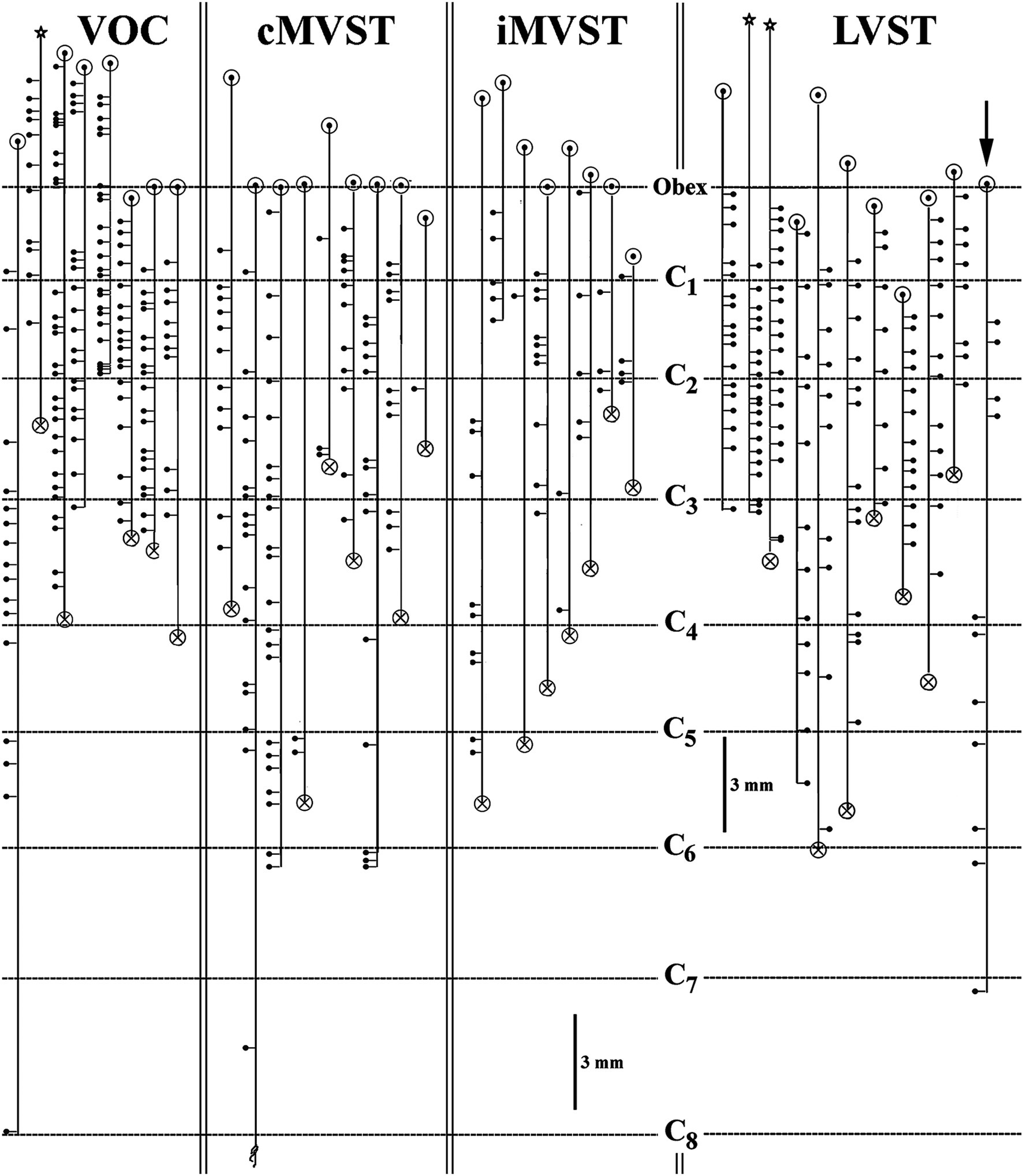
Figure 7. Branching summary for VOC (n = 8), cMVST (n = 9), iMVST (n = 8), and cervical-only LVST (n = 11) neurons. An open circle indicates the rostral extent of each recovered axon, and a circle filled with an X is the confirmed caudal location of the branch before the label fades. The star marks the location of the cell body of one VOC and two LVST neurons recovered from axon injections. The principal branch issued from the parent axon is schematically represented at each site and reflects the degree of specificity or uniformity of innervation. Three VOC, three cMVST, one iMVST, and four LVST neurons were followed to their termini. The arrow (at the far right side of the graph) designates the neuron presented in Figure 11B that showed characteristics of both LVST neurons in the upper segments and MVST neurons in the lower segments.
Complete innervation patterns of a VOC axon in the caudal brainstem (panel A) and cervical segments (panel B) are shown in Figure 8. The axon was recorded and labeled in the left ventromedial funiculus at C1 (marked by X and red arrow in B). The insert in panel B gives the cell’s identifying characteristics: the cell was antidromically activated at a latency of 1.25 ms, followed by a ~2.3 ms latency orthodromic response to shocks applied to the rostral MLF and received a monosynaptic input from the right or Vc nerve (re: axon location in the spinal cord) at a latency of 1.4 ms at threshold (12 μA) to a minimum latency of 1.2 ms (ca. 30 μA); the cell lacked any commissural synaptic drive from the left or Vi nerve or activation from C6 electrodes. In the caudal brainstem rostral to the obex (panel A; sagittal sections), the VOC axon issued four branches over a span of 1 mm to target Roller’s nucleus (RO), a precerebellar perihypoglossal nucleus (55, 56), and five more branches, again issued just rostral to the obex, that targeted the medial wall of the ventral horn (VH) near the sensory nucleus of V and the spinal V nucleus (substantia gelatinous of Rolando); four of these branches issued collaterals that continued more caudally and terminated near the C1 dorsal root entry zone (B, open circles; horizontal sections). In the cervical segments (panel B), the axon remained in the ventromedial funiculus and issued 11 branches over a 4.3 mm course before its terminus (with three minor collaterals) at C3. All branches issued off the axon and their associated collaterals projected into the medial wall of lamina VIII and had extensive arborizations in the CCN and across lamina VII often reaching the lateral border of lamina VII. An estimated 85 boutons were located in Roller’s nucleus, and 5,380 boutons were counted in its cervical projections.
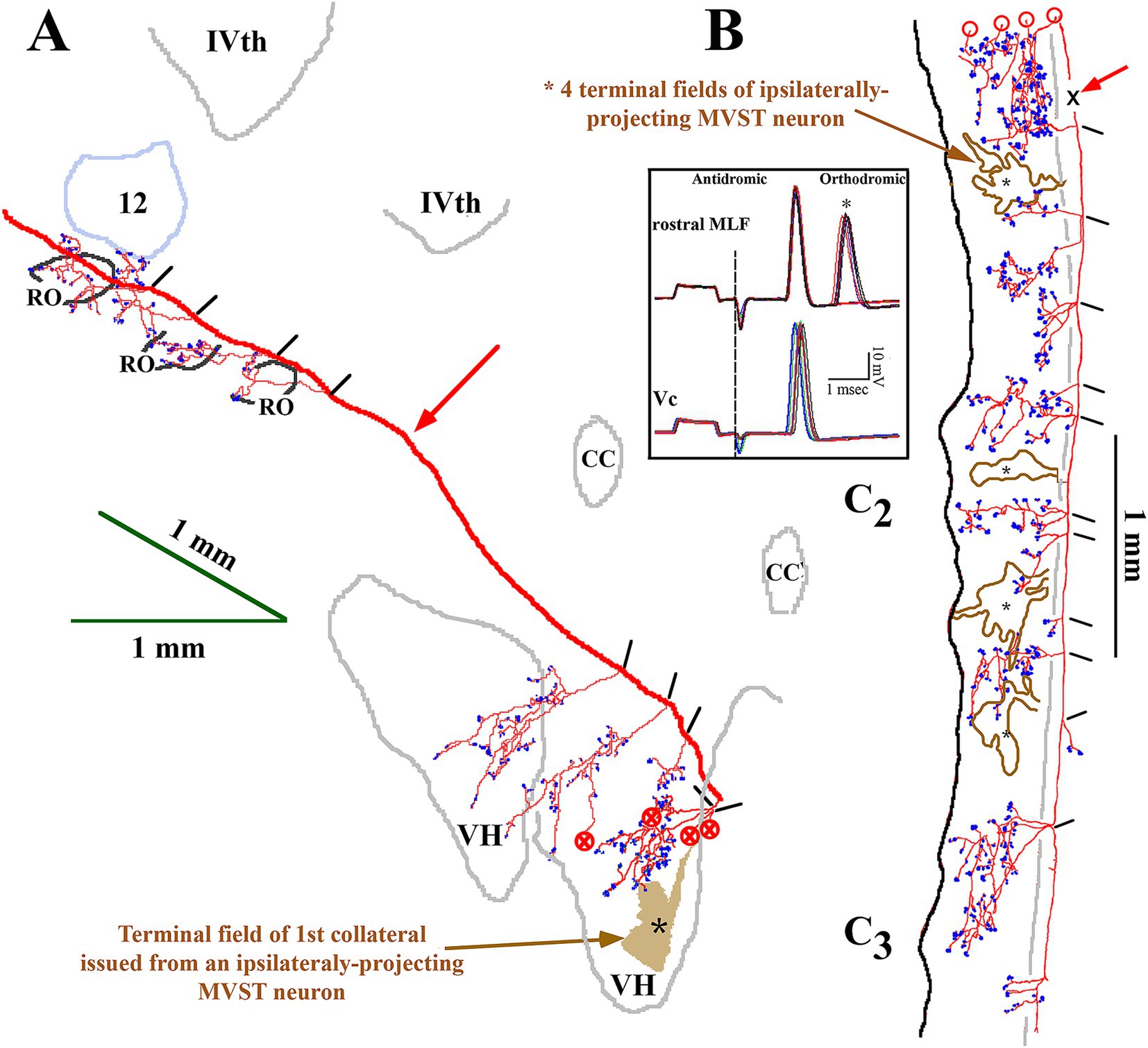
Figure 8. Extensive VOC (in red) and more confined iMVST neuron trajectories and synaptic innervation of the caudal brainstem (A) and cervical spinal cord (B). Neurons were recorded, labeled in the same experiment, and shown together for comparison. Insert box shows the antidromic activation of the VOC neuron from stimulus pulses applied to the rostral MLF, followed by an orthodromic response to an unidentified descending input in the upper trace. The lower trace in the insert shows the monosynaptic excitation from the contralateral (Vc) 8th nerve (re: axon location in the spinal cord or ipsilateral to its soma). The descending axon of the VOC issued five collaterals caudal to its soma in the brainstem, four of which targeted the precerebellar perihypoglossal Roller’s nucleus (RO) and surrounding regions. As it coursed through the caudal brainstem [red arrow in panel (A); sagittal sections] ventral to the IVth ventricle, no additional collaterals were observed until five collaterals were issued at <1 mm rostral to the obex that projected into the ventral horn (VH). The four collaterals continued caudally [marked by circles with an X in panel (A)] into the spinal cord (marked by open circles) in panel (B). The red arrow in panel (B) marks the site (X) of the VOC recording and injection. The axon’s branching and innervation patterns were consistent along its course to its terminus at C3. The other MVST cell shown in the figure was monosynaptically activated from the left or Vi nerve. The iMVST cell issued its first recovered collateral at the junction of the obex and spinal cord and had four innervation fields [*shaded field in panel (A) and *open fields in panel (B)] into dorsal motor (DM) neurons of lamina IX and throughout laminae VII and VIII. The axon could not be followed caudal to mid-C3. Open circles in B indicate the processes project rostrally and are matched to their counterparts marked by the circles filled with an X in panel (A). Calibration bars are given in each panel.
The terminal synaptic fields of a C8-projecting VOC axon are presented in Figure 9A. The cell’s axon trajectory, branching pattern, and volume of each innervation field were reconstructed in the transverse plane from horizontal sections to better visualize its projection to the ventral horn. The number below each branch is the (estimated under ×40 and ×100 oil immersion objectives) number of boutons counted in each field. The cell exhibited 15 intra-spinal branches to its terminus at C8. Unlike the VOC axon described in Figure 8 that evenly targeted equivalent cell groups along its course, this VOC displayed a preference to target cell groups in C3–C5, with negligible projection into the ventral horn of C1 and C2 and avoiding C6 and C7 altogether. The 4 terminal fields at C1 and C2 had an estimated sparse 163 boutons, whereas the remaining 11 terminal fields in C3- C5 had an estimated 1,193 boutons. Nevertheless, the branching distributions to laminae VII and VIII by VOC axons from C3 to C5 were comparable to the VOC cell of Figure 8.
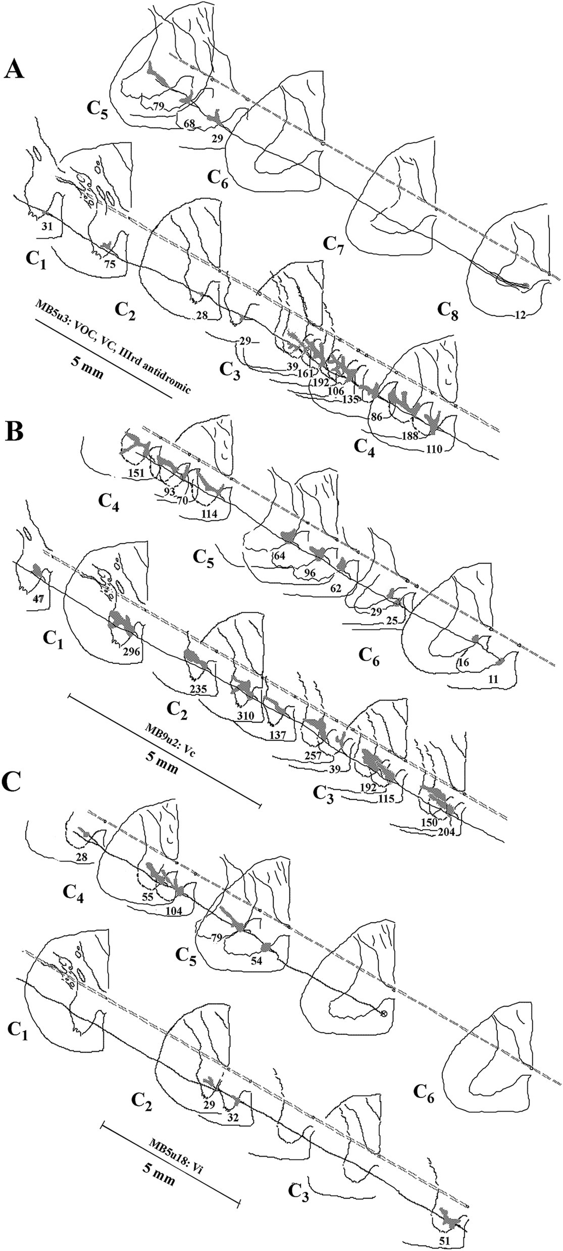
Figure 9. Comparison of the branching patterns and terminal fields of individual VOC, cMVST, and iMSVT neurons in the cervical spinal cord. (A) The VOC cell was recovered to its terminus at C8. The axon issued 15 branches that collateralized extensively to innervate the dorsal motor neurons of lamina IX, the lateral motoneuronal pool of lamina IX, and throughout laminae VII and VIII, particularly at C3–C4. (B) cMVST neuron issued 21 intra-spinal branches along its course to its terminus at mid-C6. Its innervation pattern was similar to that of the VOC cell in A, except its collaterals were more uniformly distributed along its trajectory. (C) iMVST neuron showed more restricted innervation zones that targeted mainly the medial wall of segments at C4–C5. The iMVST axon was recovered to the mid-C5 segment. Reconstructions were made initially from horizontal sections and transcribed into the transverse plane. The observed number of synaptic specializations within the terminal field is given for each branch of the individual axons.
The branching summary of the eight VOC axons is schematically depicted in Figure 7 (VOC column). The labeled axons of four VOC neurons were sufficiently traced in the brainstem rostral to the obex and had extensive innervation to the perihypoglossal nuclei and the medial reticular formation. The label of three VOC axons did not extend rostral to the obex, and the remaining axon was recovered over only a brief extent rostral to the obex. Table 1 provides quantitative measures of the VOC axons (first cell column on the left). On average, each VOC axon issued 14.75 ± 4.8 (SD) branches in the cervical segments (total 118 branches); on average, 92 ± 100 (SD) boutons were found per branch with an estimated total of 10,865 boutons. The number of branches and the estimated number of boutons encountered from the obex to C1 and within the individual cervical segments of C1–C8 are given to highlight the projection and terminal distribution. Although valid comparisons along the cells’ trajectory are not possible because only 3 of the 8 VOC axons were completely reconstructed, whereas the remaining five were partially recovered, VOC branching and terminal distributions were heavily weighted to C1–C3 ventral horn and consistently targeted laminae VII, VIII, and to a lesser extent the motoneuronal pools of lateral and ventromedial lamina IX.
Morphology of contralateral projecting MVST axonsThe identifier distinguishing cMVST from VOC neurons was the absence of an ascending branch in the rostral MLF. Figure 2 gives the soma location, initial axon trajectory, and brainstem collateralization of 2 cMVST neurons intrasomatically recorded and labeled in the ventral portion of the lateral vestibular nucleus (vLV). The neurons were monosynaptically activated by pulses applied to the left 8th nerve, antidromically activated from pulses to the C1 stimulus array but not the C6 array, and did not respond to rostral MLF pulses. The axons were recovered in the vicinity of their somas but were not visualized in the spinal cord. Thus, they are not represented in Table or Figure 7. The axon of the more lateral neuron (in red) followed an ipsilateral rostral course ~2.5 mm to cross the midline beneath the IVth ventricle and immediately issued a collateral with an estimated 12 boutons into the dorsal Raphe nucleus (*DR). The axon then traveled in the contralateral descending MLF, issued a minor branch with an estimated six boutons into the prepositus hypoglossal nucleus (*PH) at the level of its soma, and continued without branching ~1.5 mm in the brainstem until the label faded. The other cMVST neuron, with a dendritic field in both the vLV and the medial vestibular (MV) nuclei, its axon projected medially and crossed the midline at ~0.5 mm caudal to its soma and immediately issued a relatively robust projection into the prepositus hypoglossal nucleus, and the label faded.
An example of the axon path, branching pattern(s), and innervation in the ventral horn of a cMVST axon is shown in Figure 9B. Its axon issued 21 intra-spinal branches from C1 to its terminus at C6 and densely innervated the medial wall of lamina VII and VIII and in about one-half of the cases the terminal field extended throughout lamina VII and supplied the lateral motoneuronal pool of lamina IX. An estimated 2,713 boutons were counted, ranging from 11 (terminus) to 310 boutons/branch (N = 22). Although the branches were relatively evenly distributed, more synaptic specializations were seen in the upper cervical segments of C1–C4.
The branching patterns of the nine cMVST axons are schematically represented in Figure 7. The labeled axons of only two cMVST neurons were traced into the brainstem rostral to the obex, and no branches were observed; however, as seen in Figure 2, cMVST axons did innervate cell groups in the more rostral brainstem. Like the VOC axon shown in Figure 9A, one cMVST axon provided consistent innervation to the ventral horn in the upper cervical segments and bypassed C5–C7 before it terminated at C8. Table 1 provides quantitative measures of the labeled cMVST axons. In total, 90 branches were located in the cervical segments, and each cMVST axon, on average, issued 10 ± 7 (SD) branches; an estimated 83 ± 68 (SD) boutons were found on average per branch with a total of 7,751 boutons. Six of the nine (67%) cMVST distributed equally weighted innervation to the cervical segments and consistently targeted laminae VII, VIII, and lateral lamina IX.
Morphology of ipsilateral projecting MVST axonsUncrossed iMVST axons represented the least dense VS input to the cervical spinal segments. Two examples of the innervation of iMVST axons are shown in Figures 8, 9C. In Figure 8, the iMVST axon was monosynaptically excited by shocks to the left or ipsilateral 8th nerve electrodes, did not respond to C6 pulse stimulation, and the recovered axon faded at mid-C3. In the same experiment, the iMVST cell was readily distinguishable from the VOC axon. It supplied a comparable synaptic distribution into laminae VII and VIII, extending into the lateral IX, and evenly provided an estimated 268 boutons among its five branches. Figure 9C shows an iMVST innervating mainly the mid-segments of the cervical cord with a relatively lo
留言 (0)