The vestibular system senses 9 dimensions of information describing head motion and head orientation (3 dimensions each for gravity, linear acceleration, and rotation). This information plays a critical role in the maintenance of postural control, and as a result, balance assessments are commonly employed as a screening tool for vestibular dysfunction (Cohen et al., 2019). Tests of standing balance, i.e., with a fixed-base of support, rely predominantly upon the measurement of spontaneous body sway under the manipulation of sensory feedback [e.g., standing on foam, with eyes closed (Agrawal et al., 2011)]. Among the most common of these tests are (a) a standard 4-condition quiet-stance balance test that is sometimes called the Modified Romberg Test of Standing Balance (Agrawal et al., 2011; CDC, 2021) and (b) the Sensory Organization Test (Nashner and Peters, 1990), which includes anterior-posterior sway-referencing of the motion platform. However, since quiet stance balance tests manipulate balance primarily by degrading sensory feedback, we have no direct knowledge of the exact input stimuli leading to the observed postural sway. As a result, it is challenging to determine if changes in postural sway result from the precision of afferent sensory cues (including vestibular afference) or from the adoption of other exploratory or compensatory postural control strategies (Carpenter et al., 2010). This limitation has motivated the use of perturbed stance balance assessments that measure postural sway in response to a passive unpredictable motion stimulus. Unlike quiet stance, passive pseudorandom balance perturbations allow for the output of the postural control system (i.e., sway) to be described relative to a known, and consistent (across participants), input stimulus (Cenciarini and Peterka, 2006; van der Kooij and Peterka, 2011; Joseph Jilk et al., 2014; Hwang et al., 2016).
Pseudorandom support surface perturbations disturb balance using either discrete or continuous motions that are both unpredictable and independent of postural sway. Discrete perturbations are used to describe the transient postural response to an individual motion stimulus with a set frequency and amplitude (Nashner et al., 1982; Horak et al., 2016), whereas continuous perturbations are used to quantify the steady state response over a range of stimulus frequencies (Peterka, 2002). Continuous pseudorandom perturbations are often created by combining multiple sinusoids [sum-of-sinusoids, SoS (Maki et al., 1994; McAndrew et al., 2010; Sinitksi et al., 2012; Franz et al., 2015; Franz et al., 2017; Kazanski et al., 2020)] or by randomly assigning perturbation velocities to a sequence of numbers [pseudorandom ternary sequence of numbers, PRTS (Cenciarini and Peterka, 2006; Joseph Jilk et al., 2014; Pasma et al., 2015; Wiesmeier et al., 2015; van Kordelaar et al., 2018)]; each method produces an unpredictable motion trajectory secondary to the broad range of spectral components. Although a sinusoidal signal is defined by a formula, and thus, is not truly random, in the early 1960’s Stark and colleagues showed that combining as few as three thoughtfully-selected, non-harmonically related sinusoids yielded a signal that could not be predicted by either naive or experienced human participants (Stark et al., 1961). This has since been confirmed in studies of human postural control (Maki, 1987). Thus, continuous perturbation signals (SoS or PRTS) provide a robust paradigm for studying sensory contributions to balance, due to both (a) the unpredictability of the stimulus, which mitigates feedforward control mechanisms (Peterka and Loughlin, 2004), and (b) the ability to characterize postural control across a wide range of perturbation frequencies (Peterka, 2002; McAndrew et al., 2010).
Studies using 1D PRTS motion stimuli have identified specific patterns of balance dysfunction in patients with well-compensated, chronic vestibular lesions (Peterka, 2002; Peterka et al., 2011; van Kordelaar et al., 2018). As a result of these data, PRTS perturbation paradigms have been increasingly used to study vestibular, as well as other sensory, contributions to balance within a variety of different patient populations (e.g., Pasma et al., 2015; Wiesmeier et al., 2015; Campbell et al., 2022). Yet, although a great deal has been learned from the study of 1D balance perturbations, during naturalistic motion, the vestibular system does not function as a one-dimensional sensor (Wolfe et al., 2021). Instead, the collection of vestibular organs (e.g., semicircular canals and otolith organs) simultaneously sense and encode multiple dimensions of head motion stimuli that each inform unique dimensions of postural sway. As such, a multidimensional perturbed stance balance test may provide a superior method for detecting vestibular impairment by quantifying sensorimotor responses in response to rich, naturalistic multidimensional vestibular stimuli across a range of physiologically relevant frequencies. However, unlike postural responses to discrete multidirectional balance perturbations, which have been well characterized (e.g., Carpenter et al., 1999; Carpenter et al., 2001; Bloem et al., 2002; Grüneberg et al., 2005; Torres-Oviedo et al., 2006; Allum et al., 2008; Willaert et al., 2024), little is known about the steady state postural response to continuous multidimensional perturbations.
Previous groups have studied sagittal plane postural responses to combinations of pitch tilt and fore-aft translation perturbations created using either spectrally independent PRTS signals (with unique fundamental frequencies) (Grüneberg et al., 2005), spectrally independent SoS (Jeka et al., 2004), or using a combination of PRTS and SoS signals (Willaert et al., 2024). Yet, to our knowledge, the ability to quantify postural responses to a multidirectional perturbation in two orthogonal dimensions of sway (e.g., AP and ML) has yet to be investigated. To address this gap in knowledge, we developed and validated a test that uses two spectrally independent SoS signals, one for each direction of tilt (roll and pitch)—to deliver a two-dimensional (2D) balance perturbation that independently perturbed each of two spatially-orthogonal directions of sway [i.e., mediolateral (ML) and anteroposterior (AP), respectively] at different interleaved frequencies (Figure 1). We chose to utilize SoS signals, as opposed to the aforementioned PRTS signal, due to the lower degree of complexity, improved control over the stimulated frequencies, and intuitive expansion to higher dimension perturbations (e.g., 6D). Our hypotheses were (1) that during 2D perturbations, variations in the ML and AP center of pressure (CoP) would be increased primarily at frequencies coinciding with the roll and pitch platform perturbation frequencies, respectively, and (2) that the postural response during a 1D perturbation trial would be similar to the postural response measured during an identical 1D stimulus when delivered as part of a 2D perturbation.
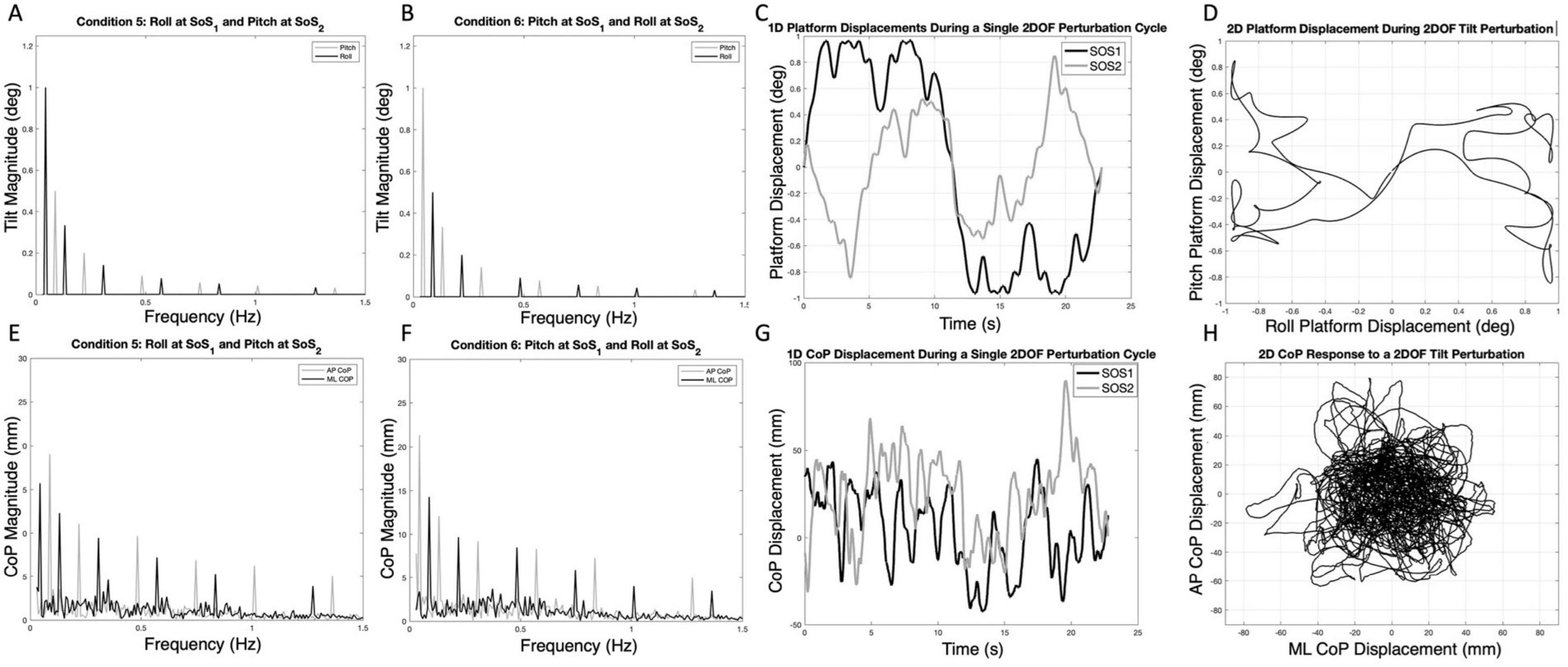
Figure 1. The spectral magnitude of the roll (black) and pitch (gray) perturbation signals are shown for each of the 2D perturbations — Condition 5 (A) and Condition 6 (B). The spectral magnitudes of the mediolateral (ML, black) and anteroposterior (AP, gray) center of pressure (CoP) responses are also shown for a single participant in each condition (E,F). The one-dimensional roll and pitch displacement time series of the platform during a two-dimensional perturbation (Condition 5) is shown in (C); here, the SOS1 signal (black) is a roll tilt, and the SOS2 signal (gray) is a pitch tilt. Exemplar one-dimensional (1D) mediolateral and anteroposterior CoP responses to the SOS1 and SOS2 perturbations are also shown in (G). The same data from (C,G) are shown as two-dimensional plots to demonstrate the two-dimensional travel of the platform (D) and the corresponding motion of the CoP for a single cycle of motion (H). Spectral plots [as are shown in (E,F)] for each of the 10 participants are provided in Supplementary Figures 2, 3.
Materials and methods Generation of the sum of sinusoids (SoS) signalsWe developed two distinct SoS balance perturbation trajectories (SoS1 and SoS2) that were orthogonal to each other in time (Figures 1A–D). This was accomplished by selecting two groups of interleaved prime numbers ( and ) and multiplying them by the fundamental frequency of 0.044 Hz (more precisely, 0.0439453125 Hz, which is a period of 22.76 s yielded by 2048 points at a sampling rate of 90 Hz). The combination of six sinusoids with independent harmonics, the use of unique phase angles for each component, and the long period of each repeating cycle (> 20 s) each add to the unpredictable nature of the SoS perturbation signal. The 90 Hz sampling rate was dictated by the device (Virtualis MotionVR) used. This yielded frequency components at the following approximate frequencies:
f=SoS1[0.044,0.132,0.308,0.571,0.835,1.274]Hz
f=SoS2[0.088,0.220,0.483,0.747,1.011,1.362]Hz
The SoS1 and SoS2 displacement trajectories (Figures 1C, D), where the subscript refers to the lowest prime multiplier used, were then created by summing sinusoidal signals using the following equations:
SoS(t)1=∑i=1ni=6A1,isin(2πfSoS1,it+∅1,i).
SoS(t)2=∑j=1nj=6A2,jsin(2πfSoS2,jt+∅2,j).
In these equations, respectively, ni and nj are the number of sinusoids in SoS1 and SoS2, Ai and Aj are the magnitudes of the i’th and j’th sinusoids in SoS1 and SoS2, fi and fj are the frequencies of the i’th and j’th sinusoids in SoS1 and SoS2, φi and φj are the phases of the i’th and j’th sinusoid in SOS1 and SOS2, and t represents time. This resulted in two SoS time trajectories (SoS1 and SoS2) that have interleaved, spectrally separated perturbation frequencies (Figures 1A, B). Since the SoS1 and SoS2 signals started with the prime numbers 1 and 2, the spectral magnitude of displacement at these lowest frequencies were larger than at the subsequent frequencies. Since the vestibular system responds primarily to velocity cues during balance (Jeka et al., 2004), the magnitude and phase (Table 1) of the individual spectral components were chosen to maintain a constant peak velocity (0.28°/s) at each perturbation frequency; this yielded displacement spectra amplitudes that varied as 1/fi across the perturbation frequencies. We varied the phase values to keep the peak-to-peak amplitude of the SoS1 and SoS2 signals within 12.4% of one another (i.e., peak-to-peak amplitudes of 1.94° for the SoS1 signal and 1.70° for the SoS2 signal) (Supplementary Figure 1). Each signal was used to perturb balance in the roll (mediolateral) and pitch (anteroposterior) dimensions separately (1D perturbations), as well as in novel 2D conditions with the SoS1 and SOS2 signals being delivered simultaneously, yielding independent frequency spectra for roll and pitch platform tilts.

Table 1. The frequency (f), amplitude (A), and phase (∅) used to create each of the sum of sines (SoS) time series are shown.
Test proceduresPostural sway data were collected in ten healthy participants (37 ± 13 years of age). Each participant denied a history of neurological disorders, as well as a history of vestibular or other sensorimotor impairments. A commercially available balance device capable of tilting the support surface ± 12° in the roll and pitch planes (Virtualis MotionVR, Perault, France) was used to perform the platform tilt perturbations. The SoS time series (described above) were first generated using a custom script written in MATLAB (v2020b, Natick, MA) and the resultant CSV files were imported into the Virtualis MotionVR Research software. Two embedded force plates captured center of pressure data at a sampling rate of 90 Hz (Figures 1E–H), which was also the frequency at which the inputs to the motion platform were provided.
Each participant completed the six conditions described in Table 2. The order of the six conditions was randomized across participants to mitigate any unintended order effects. Each condition included seven cycles of perturbations (22.76 s each) and lasted a total of 159.32 s. A narrow stance was used (1–2 cm between medial border of each foot), and each participant stood in stocking feet with arms folded at the chest. Virtual reality (HTC Vive) goggles were worn throughout; however, for the tests reported herein, the goggles displayed only a black screen to remove any visual cues. Participants were also asked to close their eyes during testing. Bose (Quiet Comfort II) over the ear active noise canceling headphones were worn and an audiobook was played throughout each trial to mask any external sounds and to help avoid boredom and keep the participant alert. The audiobook was not synchronized with the stimuli. Prior to each test condition, participants were instructed to stand “upright and relaxed,” and between each of the conditions each participant rested for at least one minute.
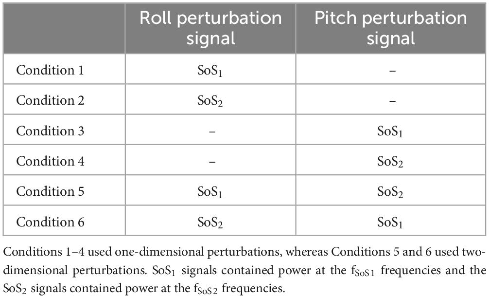
Table 2. The six test conditions are shown.
Spectral analysisCoP data were analyzed offline using a custom script in MATLAB. Consistent with existing methods used to analyze responses to PRTS perturbations, the first cycle of each trial was removed prior to the analysis to eliminate transient response components at the onset of the perturbation. The mean of each of CoP signal was first subtracted off, and then a discrete Fourier transform (MATLAB, fft.m) was applied to the remaining six cycles of zero-mean data (12,288 data points or 136.52 s) to determine the one-sided power spectra at the perturbed frequencies (fSoS1 and fSoS2). For each of the six conditions, a metric representing total ML and AP CoP magnitude was calculated by summing the CoP spectral magnitudes separately at the fSoS1 and fSoS2 perturbation frequencies. The spectral magnitude of the CoP was also determined at the non-perturbed frequencies (± 0.073 Hz) adjacent to the fSoS1 and fSoS2 frequencies. This bandwidth was chosen to provide maximum coverage while avoiding overlap with the adjacent perturbation components.
TotalMLCoPMagnitudeatfSoS1=∑i=1ni=6MLCoPMagnitude(fSoS1,i)
TotalMLCoPMagnitudeatfSoS2=∑j=1nj=6MLCoPMagnitude(fSoS2,j)
TotalAPCoPMagnitudeatfSoS1=∑i=1ni=6APCoPMagnitude(fSoS1,i)
TotalAPCoPMagnitudeatfSoS2=∑j=1nj=6APCoPMagnitude(fSoS2,j)
Frequency response functionsFrequency response functions were used to describe the magnitude and timing of postural responses relative to the tilt perturbations, as a function of frequency. A previously published method was used to estimate the angular displacement of the center of mass (CoM) (Peterka et al., 2018). The CoP data were first filtered using a digital, zero-phase 4th order Butterworth filter with a cut off of 0.47 Hz (Peterka et al., 2018). Consistent with earlier studies (Peterka et al., 2018; Campbell et al., 2022), the height of the CoM (CoMh) was estimated using standard equations (Winter, 1995) according to empirically measured lengths of the (a) leg (medial malleolus to femoral condyles), (b) thigh (femoral condyles to greater trochanter) and, (c) trunk (greater trochanter to glenohumeral joint) segments for each participant. CoM height and the ML and AP CoM displacement (CoMML and CoMAP) were then used to calculate the roll and pitch sway angles (CoMθ ,Roll and CoMθ,Pitch), respectively.
CoMθ,Roll=180π*asin(CoMMLCoMh)
CoMθ,Pitch=180π*asin(CoMAPCoMh)
The frequency response functions (FRFRoll and FRFPitch) represent the ratio between the discrete Fourier transform of the estimated CoM angles (CoMθ ,Rollor CoMθ,Pitch) and the platform tilt angles (SoSRoll or SoSPitch) at the fSoS1 and fSoS2 perturbation frequencies. From the FRFs, we calculated two metrics—the normalized response magnitude (RNorm) and phase. RNorm represents the absolute value of the complex numbers from each FRF. When the units of the input and output signals are consistent (degrees), this value is equivalent to the unitless Gain parameter (Peterka et al., 2018). Here we refer to this as RNorm, rather than Gain, to permit a consistent terminology when extending these methods to describe a postural response with units dissimilar to the perturbation stimulus (e.g., degrees of CoM sway per centimeters of platform lateral translation). Phase values, describing the timing of CoM sway relative to the platform perturbation, were calculated using the unwrap function in MATLAB which allowed the calculation of phase values beyond ± 180°(Peterka, 2002; Peterka et al., 2018). Similar to the CoP spectral magnitude, we determined RNorm and phase values at individual perturbation frequencies as well as cumulatively across the frequencies included in the SoS1 and SoS2 perturbation signals.
FRFRoll(fSoS1)=DFT[CoMRoll(fSoS1)]DFT[SoSRoll(fSoS1)]
FRFPitch(fSoS1)=DFT[CoMPitch(fSoS1)]DFT[SoSPitch(fSoS1)]
FRFRoll(fSoS2)=DFT[CoMRoll(fSoS2)]DFT[SoSRoll(fSoS2)]
FRFPitch(fSoS2)=DFT[CoMPitch(fSoS2)]DFT[SoSPitch(fSoS2)]
Time domain postural control metricsIn addition to the primary frequency domain analysis, time domain metrics — the root mean square distance (RMSD) and the mean velocity (MVELO) of the CoP — were also calculated separately for AP and ML sway in each of the six test conditions. The RMSD and MVELO metrics provide measures of total CoP sway, which includes sway in response to the perturbation, as well as sway at the non-perturbed frequencies. To calculate the RMSD, the CoP data were first low pass filtered with a 25 Hz cut off using a digital, zero-phase 4th order Butterworth filter (filtfilt, MATLAB). The ML and AP RMSD values were calculated by taking the standard deviation of the filtered and zero-mean CoP signals (Karmali et al., 2021). The mean velocity (MVELO) of ML and AP sway was calculated by dividing the CoP path length by the duration of the trial (Prieto et al., 1996).
Statistical analysisFor the 2D perturbation conditions (Condition 5 and Condition 6), paired t-tests (STATA v17, College Station, TX) were used to test for differences in the cumulative ML and AP CoP magnitudes at the SoS1 and at the SoS2 perturbation frequencies (i.e., fSoS1 and fSoS2). Prior to performing the tests, the normality of the distributions was assessed using a Shapiro-Wilk test (p > 0.05) and by inspecting normal probability plots. In addition to paired t-tests, a secondary analysis using linear mixed effect models was run for each condition to determine the difference in AP and ML sway when controlling for the six unique perturbation frequencies. To account for the four comparisons made in each of the above analyses, we report Bonferroni corrected p-values (i.e., multiplying each raw p-value by 4), with significance set at a corrected p-value of p < 0.05.
Liner mixed effect models were used to determine the effect of perturbation condition (1D vs. 2D) on the normalized response magnitude (RNorm) and phase of the sway response. To account for the repeated measures design, and to adjust for the frequency of the perturbations, each model was first run with perturbation frequency and condition as fixed effects, and participant as a random effect. Each model was then repeated with a frequency × condition interaction term, and post-hoc F tests of simple effects were run to compare 1D and 2D conditions at each of the individual perturbation frequencies. Acting conservatively, we report uncorrected p-values to provide more stringent control over Type II errors that could errantly support our hypothesis of no significant difference between 1D and 2D conditions (i.e., failure to reject the null hypothesis). In a secondary analysis, one-sample t-tests were also used to test the null hypothesis that the mean ratio between cumulative RNorm values in the 1D and 2D conditions was equal to 1 (i.e., equivalent sway response). Ratios were constructed for each individual by dividing the cumulative RNorm in the 1D task by the cumulative RNorm in the 2D task for conditions that used identical perturbation stimuli — e.g., the roll response to the SoS1 stimulus when delivered during the 1D task (Condition 1) was divided by the roll response to the SoS1 stimulus when delivered during the 2D task (Condition 5). Paired t-tests were also used to compare the CoP time domain metrics (RMSD and MVELO) between 1D and 2D conditions. As above, we elected not to correct for multiple comparisons to provide a more conservative comparison between conditions.
Results Spectral magnitude of ML vs. AP CoP in the 2D perturbation conditionsExample spectra, time traces and 2D phase plots are shown in Figure 1. The frequency spectra of the platform perturbations are shown in the upper plots (Figures 1A, B) for each of the 2D perturbation conditions (Conditions 5 and 6). Figures 1E, F show example CoP response spectra for a single participant. Figure 2 shows the average ML and AP COP sway spectra across the ten participants for the same 2D perturbation conditions. As can be observed, Figures 1E, F, 2A, B all show the existence of interleaved spectral peaks that coincide with the fSoS1 and fSoS2 perturbation frequencies.
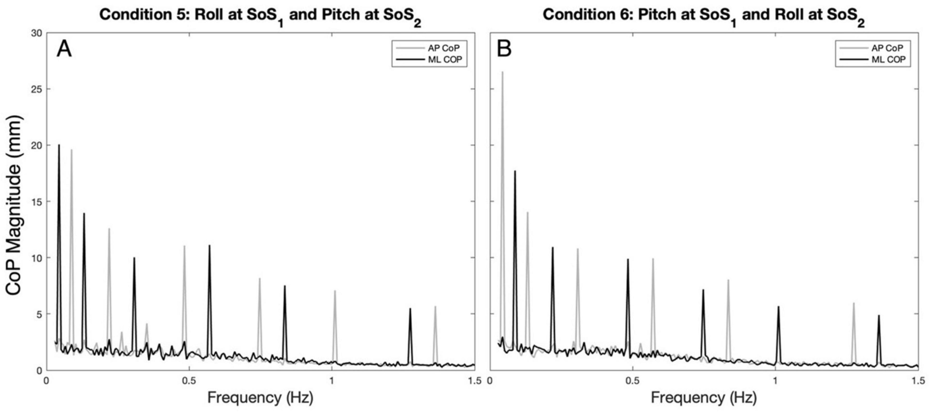
Figure 2. The average (across participants) anteroposterior (AP, gray) and mediolateral (ML, black) CoP spectral magnitudes are shown for the 2D perturbation conditions, Condition 5 (A) and Condition 6 (B). The spectral peaks occur at the frequencies (fSoS1 and fSoS2) of the two unique sum of sinusoids perturbation signals (SoS1 and SoS2).
Figures 3A–D displays the mean and standard deviation (± 1SD) of the spectral magnitude at each of the discrete spectral peaks for the 12 unique perturbation frequencies. These spectral plots show that during 2D perturbations (1) pitch perturbations yielded primarily AP sway at the frequencies of the pitch perturbations with low spectral peaks for ML sway at the same frequencies and (2) roll perturbations yielded primarily ML sway at the frequencies of the roll perturbations with low spectral peaks for AP sway at the same frequencies. To quantitatively describe the CoP response to the specific perturbation spectra (fSoS1 and fSoS2) in a single metric, we calculated the sum of the CoP magnitude across spectral peaks at the fSoS1 frequencies and, separately, at the fSoS2 perturbation frequencies (Figure 4). In Condition 5 (where the roll perturbation signal included fSoS1 frequencies and the pitch perturbation signal included fSoS2 frequencies), as hypothesized, the total ML CoP magnitude was significantly larger than the total AP CoP magnitude [t(9) = 14.46, p < 0.0001] at the fSoS1 frequencies. As hypothesized, the AP CoP magnitude was also significantly larger than the ML CoP magnitude [t(9) = 19.79, p < 0.0001] at the fSoS2 frequencies. In Condition 6 (where the pitch perturbation signal included the fSoS1 frequencies and the roll perturbation signal included the fSoS2 frequencies), as hypothesized, the ML CoP magnitude was significantly greater than the AP CoP magnitude [t(9) = 14.42, p < 0.0001] at the fSoS2 frequencies. At the fSoS1 frequencies, the AP CoP magnitude was significantly greater than the ML CoP magnitude [t(9) = 17.11, p < 0.0001] as hypothesized (Figure 4).
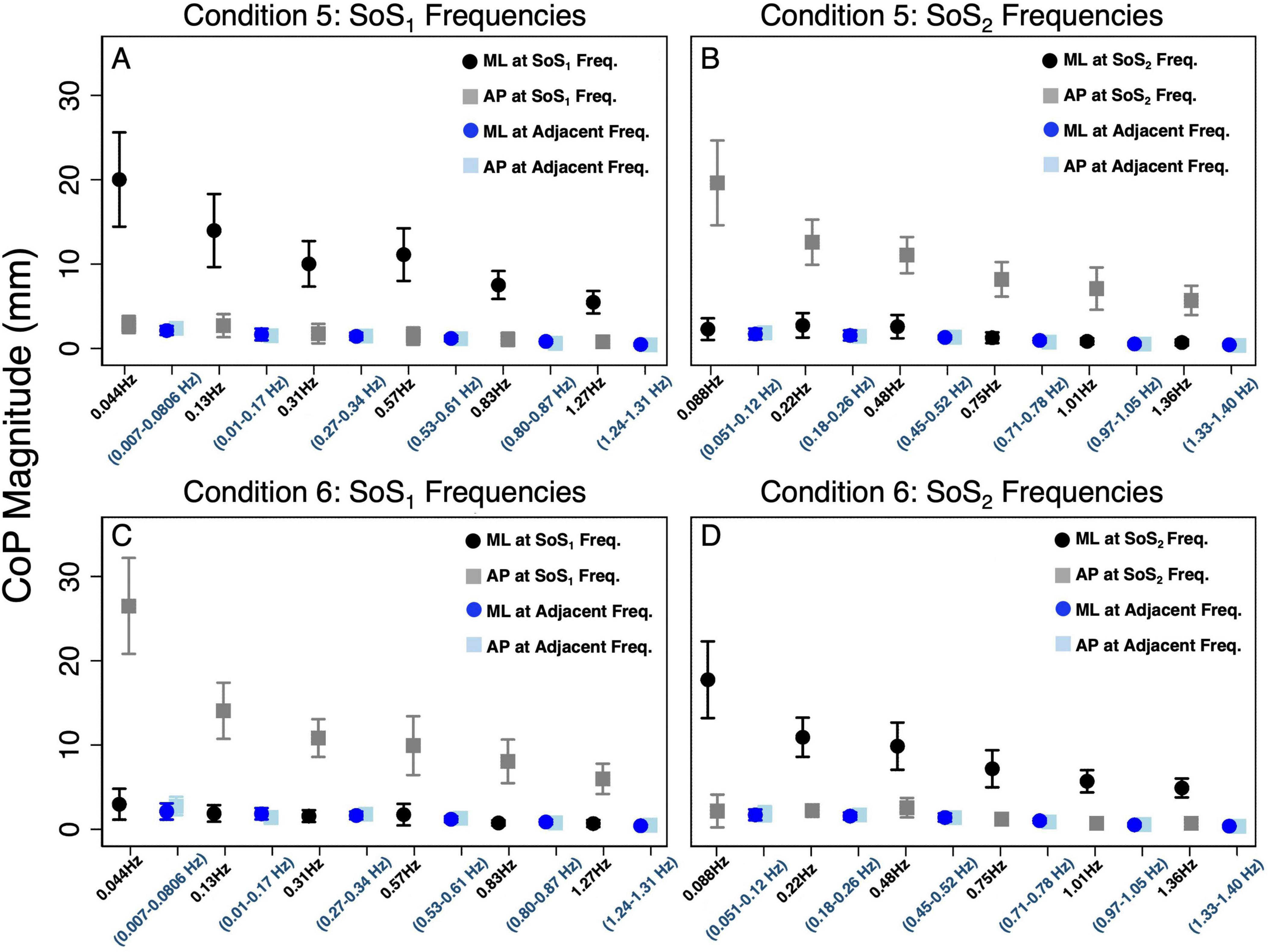
Figure 3. The average (across participants) anteroposterior (AP, gray square) and mediolateral (ML, black circle) CoP spectral magnitudes are shown for each of the stimulated frequencies in the 2D perturbation conditions. (A,B) show CoP magnitudes for Condition 5 at the SoS1 frequencies and SoS2 frequencies, respectively. (C,D) show CoP magnitudes for Condition 6 at the SoS1 frequencies and SoS2 frequencies, respectively. In each plot, the average AP (light blue square) and ML (blue circle) sway at adjacent frequencies is also shown. The adjacent sway response represents the median of the CoP magnitudes surrounding the individual perturbation frequency (± 0.073 Hz). Error bars show +/– 1 SD.
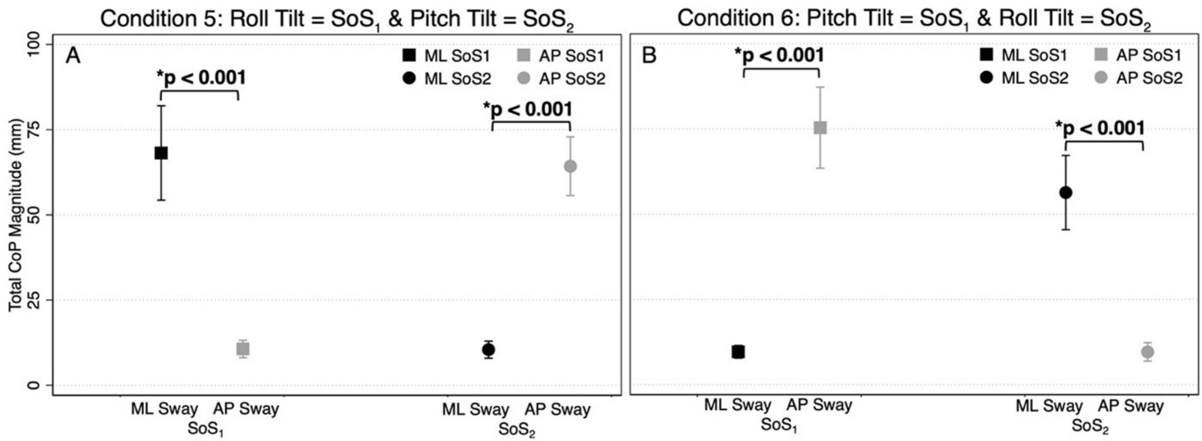
Figure 4. The total CoP magnitudes—summed across frequency — are shown for mediolateral (ML, black) and anteroposterior (AP, gray) postural sway in the 2D perturbation conditions, Condition 5 (A) and Condition 6 (B). The left side of each plot shows the mean CoP magnitude (across participants) at the SoS1 frequencies (denoted by squares), and the right side of each plot shows the mean CoP magnitude at the SoS2 frequencies (denoted by circles). Error bars show ± 1SD. Results of paired t-tests comparing the total ML and AP CoP magnitudes are shown.
Figure 3 also shows the differences in CoP magnitude at the perturbed frequencies relative to the CoP sway at the surrounding un-perturbed frequencies (calculated in the same plane of motion by taking the median value of the CoP magnitude at the ten surrounding frequencies). We repeated the above pairwise analyses to also compare the spectral magnitude at the perturbation frequencies to the spectral magnitude at the adjacent non-perturbed frequencies. We found that for each condition, the total spectral magnitude at the perturbed frequencies was significantly greater than the spectral magnitude captured in the same plane at the non-perturbed frequencies (p < 0.0001, Figure 3).
Since the difference in total CoP magnitude could be driven by a large difference only at the lowest frequencies (where much of the sway response exists), these comparisons were repeated by running four mixed effect models to determine the differences between the total AP and ML CoP magnitudes, when controlling for the six perturbation frequencies. These models yielded similar findings, showing an increase in the ML sway response at the fSoS1 frequencies in Condition 5 (β = 9.58, p < 0.001) and the fSoS2 frequencies in Condition 6 (β = 7.79, p < 0.001). Similarly, the AP CoP magnitude was larger than the ML CoP magnitude at the fSoS1 frequencies in Condition 6 (β = 10.96, p < 0.001) and the fSoS2 frequencies in Condition 5 (β = 8.97, p < 0.001). Collectively, these findings are consistent with the graphical data shown in Figures 1–4, and support that during 2D perturbations, (1) sway responses were primarily in the ML direction at the frequencies of the roll perturbation, with minimal AP frequency components at those same frequencies and (2) sway responses were primarily in the AP direction at the frequencies of the pitch perturbation, with minimal ML frequency components at those same frequencies. Individual participant data are provided in Supplementary Figures 2, 3.
Normalized response magnitude and phase in the 1D versus 2D perturbation conditionsMixed effect models were used to determine if sway responses (RNorm and phase) differed between the 2D and 1D conditions that used identical tilt stimuli with the same frequency spectra (i.e., fSoS1 or fSoS2) (Figures 5, 6). At the fSoS1 frequencies, RNorm,Roll for the 1D condition (Condition 1) was not significantly different from RNorm,Roll in the corresponding 2D condition (Condition 5) (β = 0.26, p = 0.762). Similar results were found when comparing RNorm,Roll in Conditions 2 and 6, where the roll tilt signal had power in the fSoS2 spectra (β = −0.14, p = 0.096). At the fSoS1 frequencies, RNorm,Pitch for the 1D condition (Condition 3: 15.43 ± 2.58) was found to be significantly increased relative to the 2D condition (Condition 6: 13.74 ± 2.03) (β = −0.28, p = 0.00498). When comparing Condition 4 (1D) and Condition 5 (2D) at the fSoS2 frequencies, we did not find a significant difference in RNorm,Pitch values (β = −0.11, p = 0.224) (Figures 5, 6). Each of the mixed effect models were then repeated with a frequency × condition interaction term to test for differences at each of the individual perturbation frequencies (fSoS1 or fSoS2) (Table 3). Across the 24 tests of simple effects (two conditions × six frequencies × two spectra), we found significant differences between 1D and 2D conditions at only 2 frequencies—at 0.571 Hz for the Roll SoS1 stimulus [F(1, 99) = 5.96, p = 0.0164] and at 0.0879 Hz [F(1, 99) = 5.31, p = 0.0233] for the Pitch SoS2 stimulus (Figures 5, 6). The average differences in RNorm,Roll and RNorm,Pitch between the 1D and 2D conditions across the six frequencies are shown in Table 4. In addition, Figures 5, 6 shows an overlapping of the error bars (± 1SD) for the 1D and 2D conditions at each of the individual perturbation frequencies.
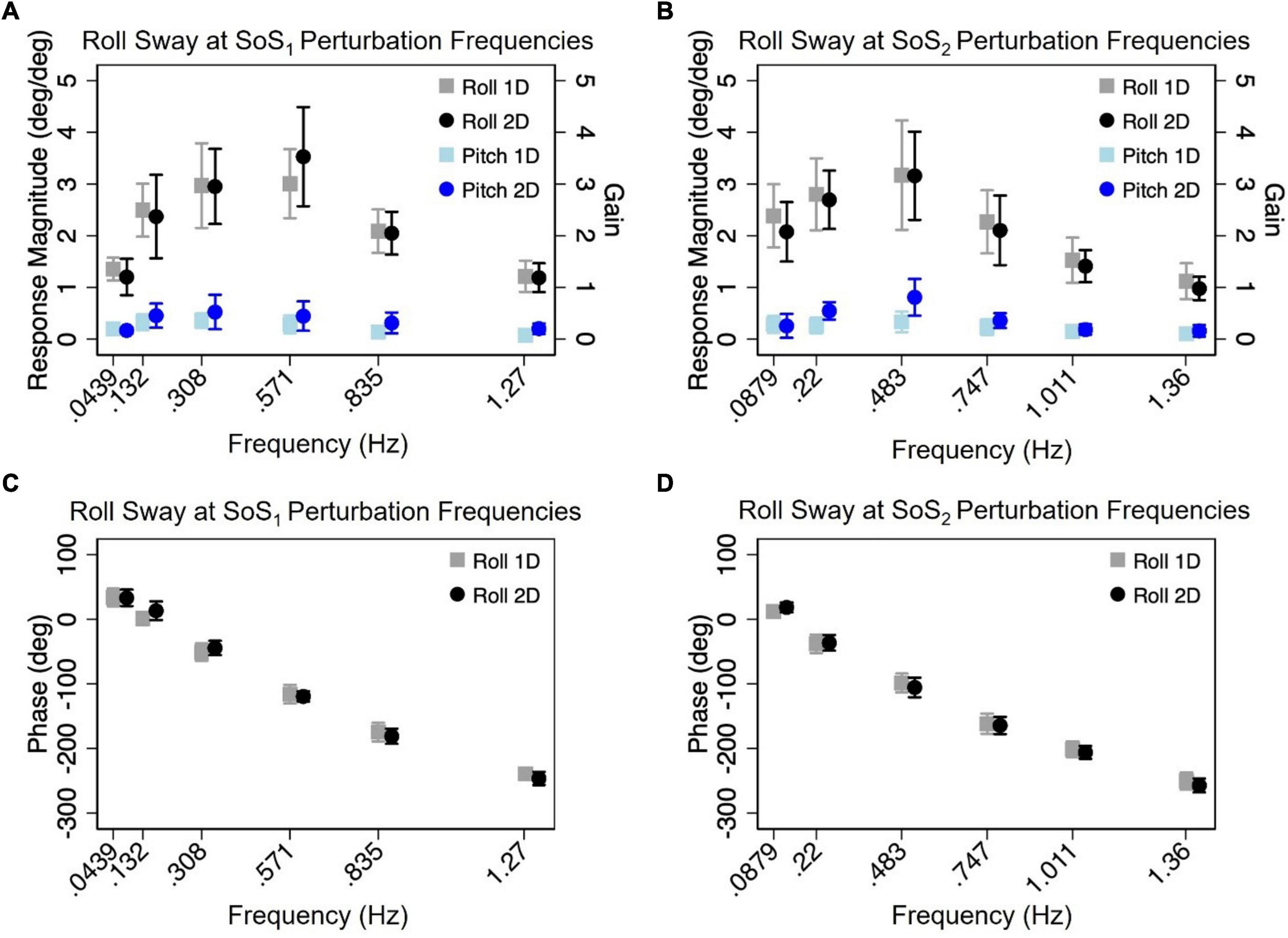
Figure 5. The mean (across participants) normalized response magnitudes (A,B) and phases (C,D) of the center of mass (CoM) in the roll plane are shown for the 2D (black circle) and 1D (gray square) roll perturbation conditions, at each of the individual fSoS1(A,C) and fSoS2(B,D) frequencies. The magnitudes of the off-axis pitch plane responses at the roll perturbation frequencies are also shown for 1D (light blue square) and 2D (blue circle) conditions. Error bars show ± 1SD surrounding the mean.
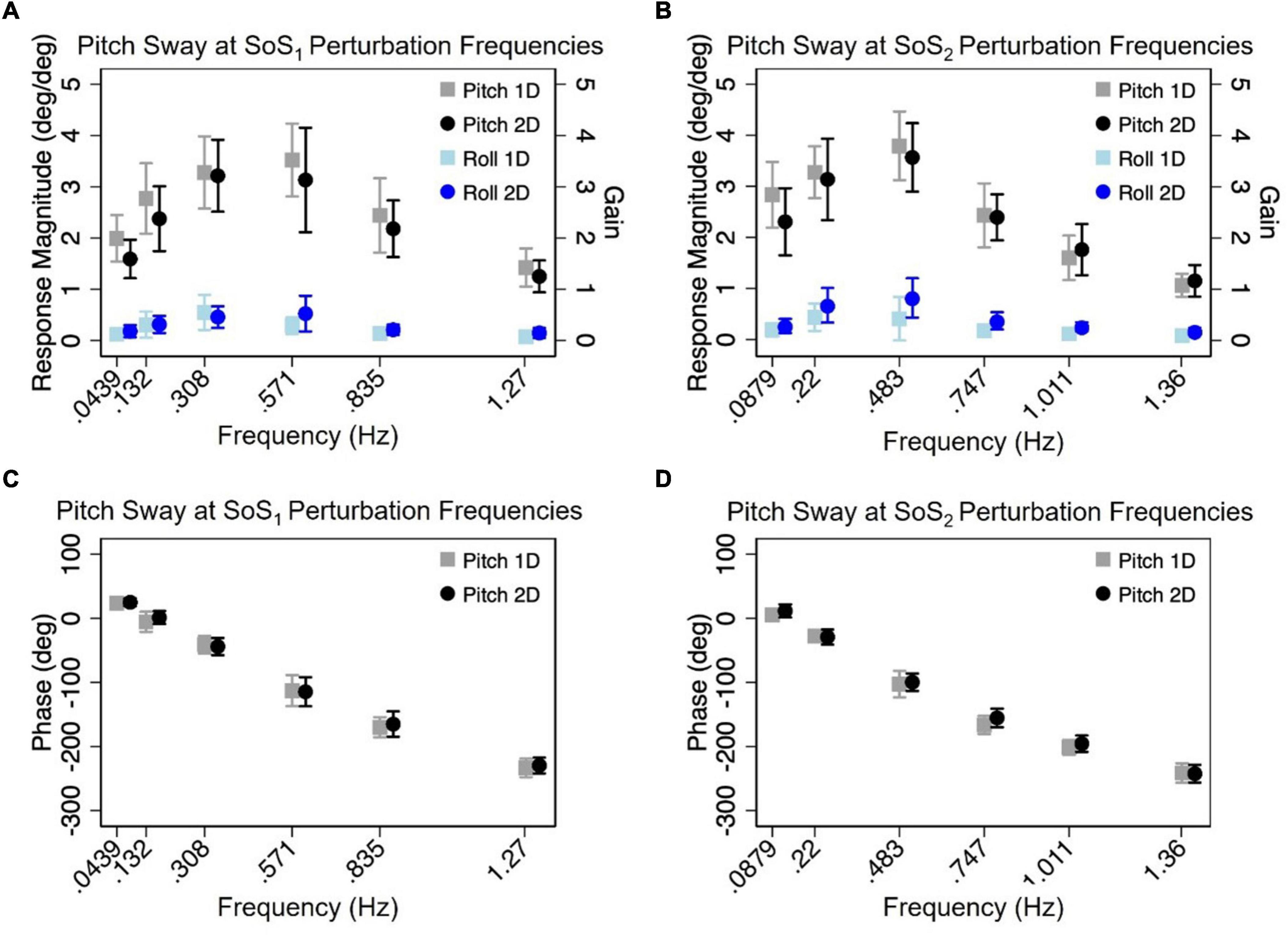
Figure 6. The mean (across participants) normalized response magnitudes (A,B) and phases (C,D) of the center of mass (CoM) in the pitch plane are shown for the 2D (black circle) and 1D (gray square) pitch perturbation conditions, at each of the individual fSoS1(A,C) and fSoS2(B,D) frequencies. The magnitudes of the off-axis roll plane responses at the pitch perturbation frequencies are also shown for 1D (light blue square) and 2D (blue circle) conditions. Error bars show ± 1SD surrounding the mean.
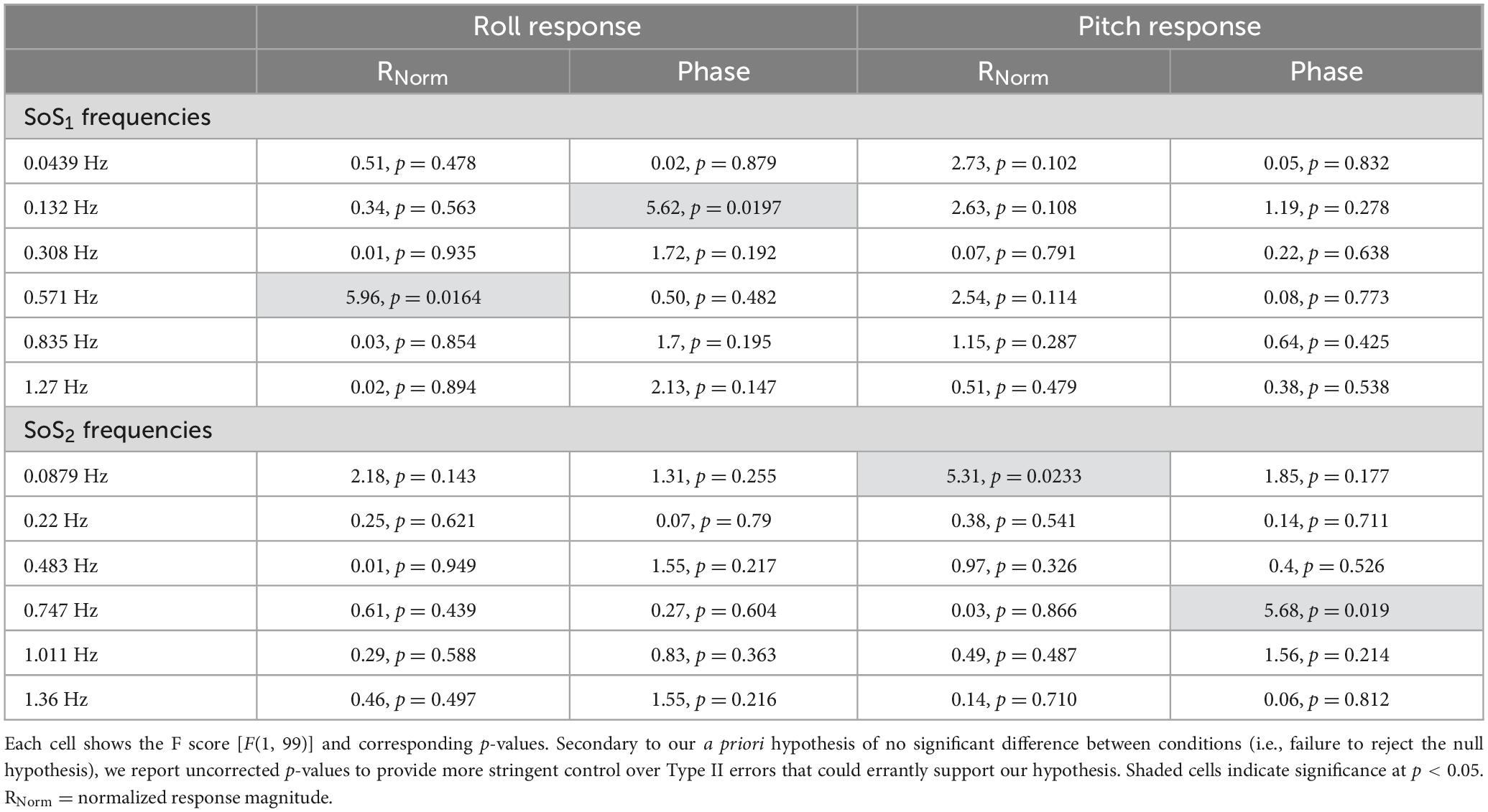
Table 3. After each mixed effect model, 2D and 1D tasks were compared at each of the individual perturbation frequencies using post-hoc tests of simple effects.
留言 (0)