
記住我
Fourteen fresh frozen human femora from female donors older than 60 years were included in this study. Only intact bones without any pathologic deformities or prior implant fixations were accepted. All femora were CT scanned to determine bone mineral density (BMD) by converting the measured Hounsfield units into density (mg/ccm) based on calibration with a phantom (European Forearm Phantom). The center of the femoral head was identified and the slices were aligned perpendicular to the neck axis. Within the cancellous bone structure, two slices in each direction were averaged to determine BMD in the femoral head. The specimens were evenly distributed into the test groups (axial notch dynamization n = 7; standard treatment n = 7) based on the BMD.
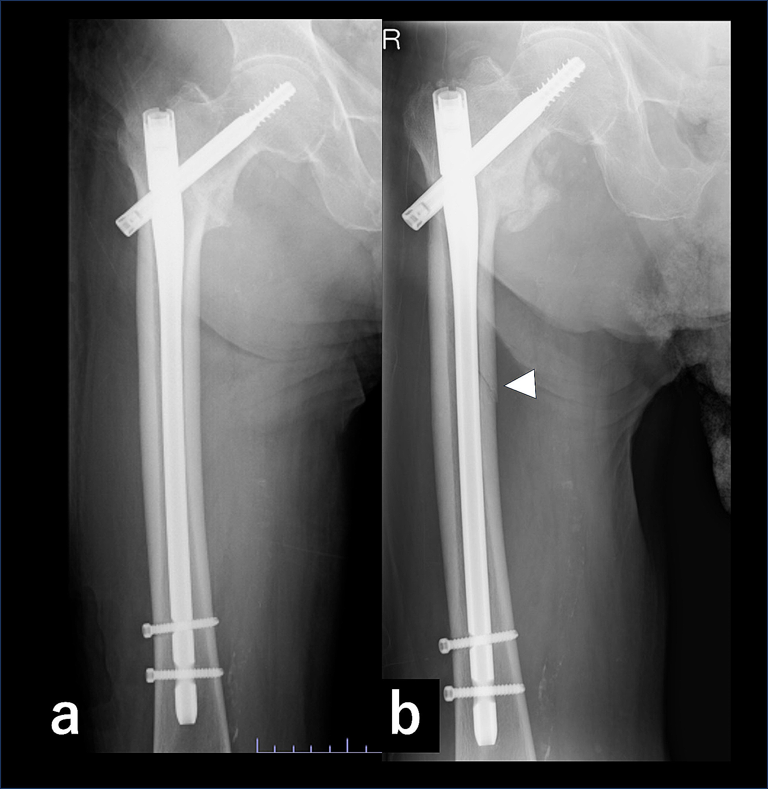
Specimen preparationThe specimens were stored at -20° Celsius and thawed overnight before preparation. Soft tissue was dissected and the femora were prepared according to the surgical technique by reaming the medullary canal and by drilling the hole for the lag screw in the intact bone first. Then, using a custom-made sawing template, a series of reproducible proximal femur osteotomies were performed to simulate an unstable pertrochanteric fracture with a lateral wall thickness of the greater trochanter less than 20.5 mm (AO/OTA 31A2.2). The calcar wedge including the lesser trochanter was removed completely (Fig. 1). Additionally, the specimen was cut at 25 cm, measured from the superior aspect of the femoral head.
Fig. 1
Unstable pertrochanteric fracture (AO/OTA 31A2.2) with a calcar wedge in frontal view (a); axial notch dynamization concept by tapping the lateral cortex indicated by the arrow (b)
After osteotomy, implantation of the nail followed (Hansson DCN, 180 mm, 125°, ø 11 mm, Swemac, Sweden). The length of the lag screw (ø 10.75 mm) was measured intraoperatively and lag screw position in the subchondral region was ensured and controlled by radiographs. The set screw was tightened manually according to the manufacturer recommendations and end caps were omitted in this in-vitro study. In the group with axial notch dynamization (n = 7), dynamization along the shaft axis was enabled by tapping the lateral cortex below the head of the lag screw according to the manufacturer’s recommendation. Via a guided drill sleeve, the dynamization notch was tapped to the same diameter as the lag screw (Fig. 1b). Distally, the fully threaded locking screw (ø 5 mm) was inserted in the dynamic nail hole and ensured bicortical fixation. After implantation, each bone was aligned at 17° adduction and 11° flexion, to simulate loading at heel strike [11]. Distally the specimens were embedded in an aluminium pot using polyurethane (RenCast FC 53 A/B + filler DT 082, Huntsman; The Woodlands, TX, US).
Mechanical setupMechanical tests were conducted on an electrodynamic testing machine (Instron E3000, Instron GmbH, Darmstadt, Germany). Physiological loads were applied on the femoral head via a conical load applicator that was attached to a multidirectional bearing plate and the load cell of the machine actuator (Fig. 2).
Fig. 2
Mechanical loading of the specimen via a conical load applicator attached to a multi-directional bearing plate and the machine actuator. Reference marker clusters defined the alignment of the coordinate system and interfragmentary motion was analyzed based on four marker flags attached to anatomical landmarks
Cyclic testing was performed under stepwise increasing axial load until failure. To settle the construct, the specimens were preconditioned for 100 cycles at a sinusoidal load between 50 and 500 N at a frequency of 2 Hz. After that, a quasi-static ramp at a velocity of 0.1 mm/s up to a load of 500 N was conducted to determine initial construct stiffness.
In a next step, cyclic sinusoidal loading at a frequency of 2 Hz started between 50 and 500 N. Every 20,000 cycles, the upper load level increased stepwise by 100 N. At the end of each load level, cyclic loading paused, and the quasi-static stiffness measurement was repeated up to the respective upper load level.
Interfragmentary motion was analyzed with a 3D optical motion tracking system (ARAMIS 5 M, GOM GmbH, Braunschweig, Germany) and pictures were taken at the lower load level of 50 N and the respective maximum load for each load level. To guarantee same marker positions for each specimen, anatomical landmarks were identified. Marker flags were positioned at the femoral head, on both sides along the fracture line and the shaft. Additionally, two reference clusters were installed. The first one represented the coordinate system in space. The second marker cluster defined three coordinate systems and was aligned according to the orientation of the femur (17° adduction / 11° flexion). The first one was in line with the axis of the femoral shaft. The second one was in line with the fracture through the trochanter and the third one was in line with the lag screw. In reference to the respective coordinate system varus collapse, posterior rotation and longitudinal sliding of the head fragment along the fracture line was measured with respect to the rigid greater trochanter fragment.
Cyclic loading was terminated at 20 mm actuator displacement, implying one of the following catastrophic failure modes: varus collapse, excessive subsidence or rotation of the head fragment, bone or implant breakage. Failure load, failure mode, cycles to failure, construct subsidence and head rotations were recorded and analysed.
Data analysisResults for construct stiffness and interfragmentary motion were reported as mean values with 95% confidence intervals, and all other results were given as mean ± standard deviation. Subsidence of the head fragment during preconditioning, was measured based on the unloaded states before and after 100 settling cycles. Based on the slope of the linear portion of the load-displacement curve, axial construct stiffness was analysed. After every 20,000 cycles stiffness calculation was repeated. Subsidence of the head fragment along the fracture line, varus collapse and posterior rotation of the head fragment were investigated using the respective coordinate system.
For statistical analysis data were tested for normal distribution using Shapiro Wilk tests (SPSS Statistics, Version 26, IBM, Armonk, NY, USA). BMD and cycles to failure were compared using Mann-Whitney-U tests and further analysed using a Pearson correlation. A Kaplan-Meier survival analysis with log-rank test was applied to evaluate cycles to failure. Axial construct stiffness and interfragmentary motion were compared using unpaired t-tests and analysed at 120,000 load cycles, equivalent to 1100 N, which was the maximum load level of the weakest construct. Level of significance was set to 0.05.
留言 (0)