
記住我


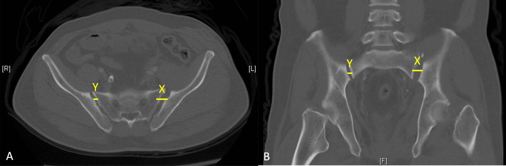
The patient was an 87-year-old male who suffered an anterior column and posterior hemitransverse fracture of the right acetabulum through a simple fall (Fig. 1). Informed consent regarding the innovative nature of the technique was obtained from the patient. The patient was informed about alternative therapies and received an individual information sheet. The surgical procedure was planned and performed in an interdisciplinary setting by an experienced orthopedic surgeon and a urologist. The study was approved by the Medical Ethics Committee of our institution (University Ethics Committee No. 248/18).
Fig. 1
The illustration displays the 3D reconstruction of the fracture morphology based on preoperative CT imaging. The image revealed an anterior column and hemitransverse fracture of the right acetabulum
ApproachThe patient is placed in a supine position on a carbon table that allows easy imaging by image intensifier fluoroscopy. Before surgery, fluoroscopic AP, inlet, outlet and Judet oblique views X-rays were obtained to ensure adequate visualization of the fracture site. A supraumbilical longitudinal incision was made to insert the 8 mm camera trocar. This was followed by visualization of the fascia and puncture of the abdominal cavity using a Veress needle. After elevating the abdominal wall and verifying its correct positioning, CO2 was insufflated to a pressure of 12 cm H2O. Subsequently, a second camera trocar was introduced cranially to the navel. Working trocars for the manipulator were positioned approximately 9 cm lateral to the midline just below the navel. The lateral screws, for example, could also be inserted via this access during the operation, so that no further accesses were necessary. The 4th trocar for the manipulator was placed level with the camera trocar, 9 cm from the other trocar on the left side. Lateral and medial to the right trocar, another two trocars (12 and 5 mm) were placed slightly more cranially. The position was then adjusted to a head-down tilt, and the DaVinci system was used for docking. Figure 2 shows an overview of the placement of the Da Vinci robot in the operating theater.
Fig. 2
The figure shows the placement of the DaVinci robot in the operating theater during the preparation of the surgical site by the urological surgeon
Surgical techniqueThe operation began with the placement of a Steinmann screw (DePuy Synthes, Raynham, MA, USA) in the right femoral neck. Under fluoroscopic control, height localization was achieved. A surgical incision was made on the lateral thigh, below the trochanter, and a Steinmann screw was placed in the femoral neck.
Then, the dorsolateral parietal peritoneum was incised, allowing for the predominant blunt presentation of the Cavum Retzi and the right fossa. The bladder was retracted medially, and the peritoneal sac was retracted cranially. Dissection of the external iliac artery commenced at the internal inguinal ring and continued to the origin of the internal iliac artery. Both vessels were looped. Two dorsally running vessels (smaller vessels) were ligated, enabling the external iliac vein and artery to be mobilized laterally and cranially for subsequent plate placement. A significant amount of fatty tissue was found in this area. The lymphatic channels were coagulated, and the medial lymphatic bundle was clipped distally. The lymphatic tissue was then rolled off the vein, revealing the obturator fossa. A hematoma was observed here. Further deep dissection was performed to expose the femoral head. The hematoma was flushed and debrided.
A skin incision of approximately 3 cm in length was made horizontally above the symphysis. Subcutaneous dissection was carried out with successive hemostasis. Dissection continued until the fascia was reached, followed by the placement of a trocar. Meticulous dissection along the superior pubic ramus and the infrapectineal line was performed dorsally up to the sacroiliac joint. The ‘corona mortis’ was identified and ligated using clips. The obturator vessels were identified and preserved. The quadrilaminar surface, which was notably protruded and internally fractured, was cleaned of hematoma. The area was then flushed for a better overview.
ReductionWhile traction was applied to the right leg using the Steinmann screw, the fragment complex was repositioned laterally with concurrent pressure applied using a ball-tipped probe. Ultimately, anatomical repositioning was achieved, and the device was secured using a 1.8 mm K-wire. Another K-wire was placed directly under visualization below the external iliac vein and artery to keep the vessels aside. Figure 3a-b shows the intraoperative X-rays before and after reduction.
Fig. 3
The left image (3a) displays the intraoperative X-ray image without repositioning. The right image (3b) shows the initial repositioning under traction applied by the Steinmann screw
FixationThrough suprapubic access, a suprapectineal plate (Pro pelvis and Acetabular System, Stryker, MI, USA) is placed endoscopically below the vessels. Figure 4 illustrates the intraoperative placement of the plate via the suprapubic approach. Currently, under endoscopic guidance, placement starts with a ventral screw, which is occupied with appropriate 3.5 mm cortex screws. After the insertion of the first screw, which was not fully tightened, the plate position could be finely adjusted. Subsequently, the first screw was fully tightened, and the plate was further secured with additional screws in the usual manner (3 near the symphysis and 3 in the ilium).
Fig. 4
Placement of the plate in the operating theater via the suprapubic approach
All screws had good anchorage in the bone at the final stage. Fluoroscopic control (A.P., lateral, iliac, and obturaor) revealed good implant positioning and, considering fragmentation, satisfactory reduction. There was no intra-articular friction when moving the joint. The operation took 312 min and the blood loss was approx. 250 ml.
AftercareNo weight-bearing was allowed for the affected lower extremity six weeks after surgery. Follow-up examinations and X-ray control were performed after 6 and 12 weeks. Figure 5 shows the postoperative X-ray image of the patient who underwent inserted osteosynthesis. There was no restriction on the mobility of the affected joints, and patients were allowed to sit up straight. We recommended consequent physiotherapy and applied thrombosis prophylaxis with low-molecular heparin until full remobilization. The patient did not suffer any postoperative complications and the healing process was regular.
Fig. 5
Preoperative X-ray image showing the fracture on the left and postoperative X-ray image showing the correctly positioned implant on the right
留言 (0)