

記住我


Recently, CPG models, such as neuron-based CPG model (Saito et al., 2009; Katayama, 2012; Dingguo et al., 2017; Ferrario et al., 2018; Payam et al., 2018; Xie et al., 2019; Mokhtari et al., 2020; Pasandi et al., 2022; Wei et al., 2022) and oscillator-based CPG model (Conradt, 2003; Acebrón et al., 2005; de Pina Filho et al., 2005; Morimoto et al., 2008; Mora et al., 2012; Fu et al., 2018), are used for imitating the swing angles of human lower limbs. The former utilizes an oscillator to imitate the functions of neural cells, while the latter utilizes an oscillator to imitate periodic motions/torques. Therefore, the CPG models based on non-linear oscillators are more widely used for describing human walking than those based on neurons because of their simpler structure. Conradt (2003) proposed a CPG model based on the Kuramoto oscillator for a serpentine robot and achieved walking control during various environments. Morimoto et al. (2008) designed a CPG model of a humanoid robot and was able to simulate biped walking. Mora et al. (2012) designed a rhythmic gait generator for a mechanical walking apparatus by establishing a CPG model based on the van der Pol (VDP) oscillator and imitated hip and knee motions during walking. Nandi et al. (2008, 2009) proposed a CPG method for modeling a biped robot. de Pina Filho et al. (2005) applied a CPG model based on the Rayleigh oscillator for prosthesis control. However, the abovementioned CPG models are unable to precisely imitate asymmetric time ratios of human hip motions in their sagittal plane because they generate trajectories with a symmetrical time ratio. The asymmetric time ratios of hip joint mean that the duty of the forward progress is different from the duty of the backward progress within one period.
In this article, to achieve the asymmetric time ratio of the trajectories of human hip joints and to simulate the coupling relationship between human hip motion and knee motion, a cardioid oscillator based on a cardioid oscillator-based CPG (COCPG) model is designed by the authors (Fu et al., 2018) to imitate the swing angles of human lower limbs. The dynamic characteristics, such as the symmetry, self-excitation, astringency, and anti-interference of the COCPG, are numerically analyzed. Furthermore, the influence of the COCPG model's parameters on the frequency, amplitude, and offset are also numerically simulated and analyzed. Additionally, the trajectories generated by the COCPG model are compared with those experimentally measured from a tester in experiments and generated by the CPG model based on the Rayleigh oscillator.
For convenience, human lower limbs are usually considered as two double pendulums with four degrees of freedom (DOF) as shown in Figure 1A. As Figure 1A shows, the motions of the lower limbs include the swing angles of two hip joints and two knee joints, which are marked as Ang_H_Right, Ang_H_Left, Ang_K_Right, and Ang_K_Left, respectively. The motions of the lower limbs are asymmetric and coordinated, which means that four swing angles have asymmetric time ratios and pairwise coupling. Therefore, to imitate the motion of lower limbs, the COCPG model, whose principle is shown in Figure 1B, is proposed in this article.
As shown in Figure 1B, the proposed COCPG model is composed of a hip motion generator and a knee motion generator for imitating the motions of two hip joints and two knee joints, respectively. In particular, to imitate the behaviors of the Hip_Left joint and the Hip_Right joint, which are coupled with another, a hip motion generator is designed using two coupled cardioid oscillators (COs) through the oscillating terms L1 and L2 to generate the trajectories of Ang_H_Right and Ang_H_Left with locked phases. The cardioid oscillator shown in Figure 1B is an oscillator with an asymmetric limit cycle about the center proposed by the authors in a previous study (Fu et al., 2018). Correspondingly, the knee motion generator established by two mapping functions G1 and G2 generates two swing angles of the knee joints, Ang_K_Right and Ang_K_Left. Since the two mapping functions G1 and G2 are introduced from the Hip_Left CO and the Hip_Right CO, which are coupled, the functions G1 and G2 are coupled with one another.
The CO shown in Figure 1B is a non-linear oscillator whose limit cycle is a cardioid curve. Since the cardioid curve is a kind of asymmetric curve about its center, the CO can generate the trajectories with asymmetric time ratios.
is a closed cure of the system A.
where a, b, c are the parameters for adjusting the asymmetric of the curve.
When a, b, and c are equal to 5, 200, and −4, respectively, curve C in phase plane is shown in Figure 2.
as t → ∞.Substituting Equation (14) into Equation (15) leads to
∂F∂x1g12+∂F∂x2g22≤0. (16)According to Equations (11, 16), g11, g12, g21, and g22 can be given by
+σi(x1′j+ x2′j)x2′ix2′iD11ω x2˙′=k-σi(x1′j+ x2′j)x1′ix2′iD22ω. (23)Considering the states x1′ and x2′ of the CO as the hip angle and velocity of the CPG model, respectively, we have
Fitting the hip angle and the knee angle of a natural gait, the mapping function G between the hip motion and the knee motion can be defined as
G( Ang_H ,Vel_H)=(Vel_H-Ang_H+θ)2 (26)where θ is a constant.
From Equations (22–26), the COCPG model can be expressed as
+σ(x3′+ x4′)x2′2D11ωx2˙′=k-σ(x3′+ x4′)x1′x2′D22ωx3˙′=-k+σ(x1′+ x2′)x4′2D11ωx4˙′=k-σ(x1′+ x2′)x3′x4′D22ωAng_H_Right=x1′Ang_K_Right=(0.05(x2′-0.8x1′)+θ)2+P3Ang_H_Left=x3′Ang_K_Left=(0.05(x4′-0.8x3′)+θ)2+P3. (27)As Equations (11, 22, 27) show, the parameters a, b, and c of the COCPG model can be used to adjust the shape of the limit cycle, γ can be used to adjust the convergence rate of the trajectory generated by the COCPG model, ω can be used to adjust the frequency, D11 and D22 are used to adjust the amplitude, and P1 and P3 can be used to adjust the offset. Therefore, by choosing appropriate values of the mentioned parameters, the rhythmic motions of lower limbs with different frequencies and amplitudes can be imitated by the proposed COCPG model given by Equations (21, 22, 27).
3 Numerical simulations and analyses 3.1 Behaviors of the cardioid oscillatorIn this section, the behaviors of the CO, such as asymmetry, self-excited oscillation, anti-interference, and convergence, are analyzed using numerical simulations.
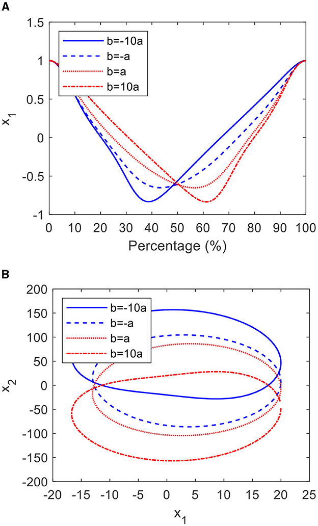
3.1.1 AsymmetryFrom Equation (18), it is clear that the shape of the CO can be adjusted through parameters a and b. When a equal to 5, c equal to −4, and b equal to −50, −5, 5, 50, respectively, the graphs and phase planes are shown in Figure 3. It can be seen from Figure 3A that as b increases from −50 to 50, the proportion of the forward progress significantly increases by 24%. Meanwhile, the shape of the limit cycle becomes increasingly asymmetric, as shown in Figure 3B.
Figure 3. The cardioid oscillator with verified b: (A) the graphs and (B) the limit cycles.
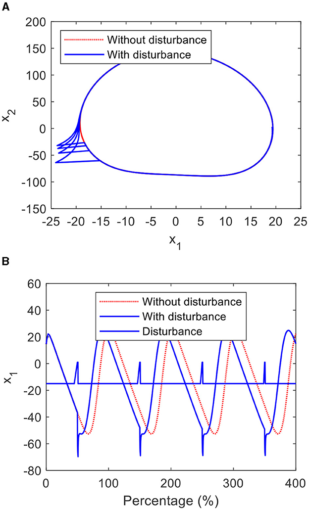
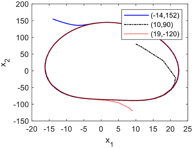
3.1.2 Anti-interference and self-excitementFigures 4A, B show the phase plane and graph of the CO, which is perturbed by a disturbance signal with the amplitude of 45. From Figure 4, it is clear that the states of the CO deviate from the limit cycle when the CO is disturbed by the pulse signal and return to the limit cycle in a short time. From Figure 5, it can be seen that when the initial conditions of the CO equal to (−14, 152), (10, 90), and (19,−120), their states autonomously converge to the limit cycle, even though these initial conditions deviate from the limit cycle.
Figure 4. Limit cycles and graphs of the CO: (A) the limit cycles and (B) the graphs.
Figure 5. Limit cycles of the CO with different initial conditions.
The results indicate that the CO has a stable limit circle to lead a stable trajectory of the lower limb.
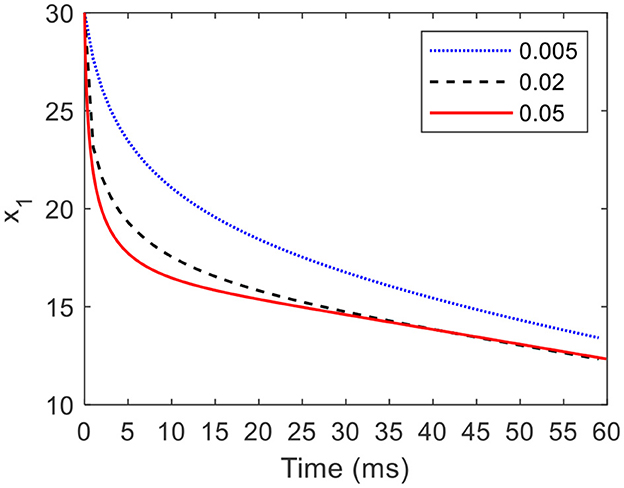
3.1.3 Convergence rate of the cardioid oscillatorAccording to Equation (18), when an initial condition is (30, 0), a = 5, b = 200, and c = −4, Figure 6 shows the partial graphs of the CO with γ of 0.005, 0.02, and 0.05. When γ is equal to 0.005, it takes 15 ms for state x1 converging from the initial condition where x1=30 to the limit cycle where x1=20. As γ increases to 0.02, the required time of the converging process decreases to 5 ms. Furthermore, when γ is increases to 0.05, the required time of the converging process decreases to 2 ms.
Figure 6. Partial graphs of the CO with different γ values.
The results indicate that the COCPG model provides a strong response to the environment changes.
3.2 Numerical simulations and analyses of the COCPG modelIn this section, when modeling the motions of lower limbs with different frequencies and amplitudes, the influence of the parameters of the COCPG model on the frequency, amplitude, and offset of the trajectories generated by the COCPG model are numerically simulated and analyzed. When modeling the motions of lower limbs, the parameters a, b, and c in Equation (27) are equal to 5, 200, and 2, respectively, k is 0.64, and γ is 0.02.
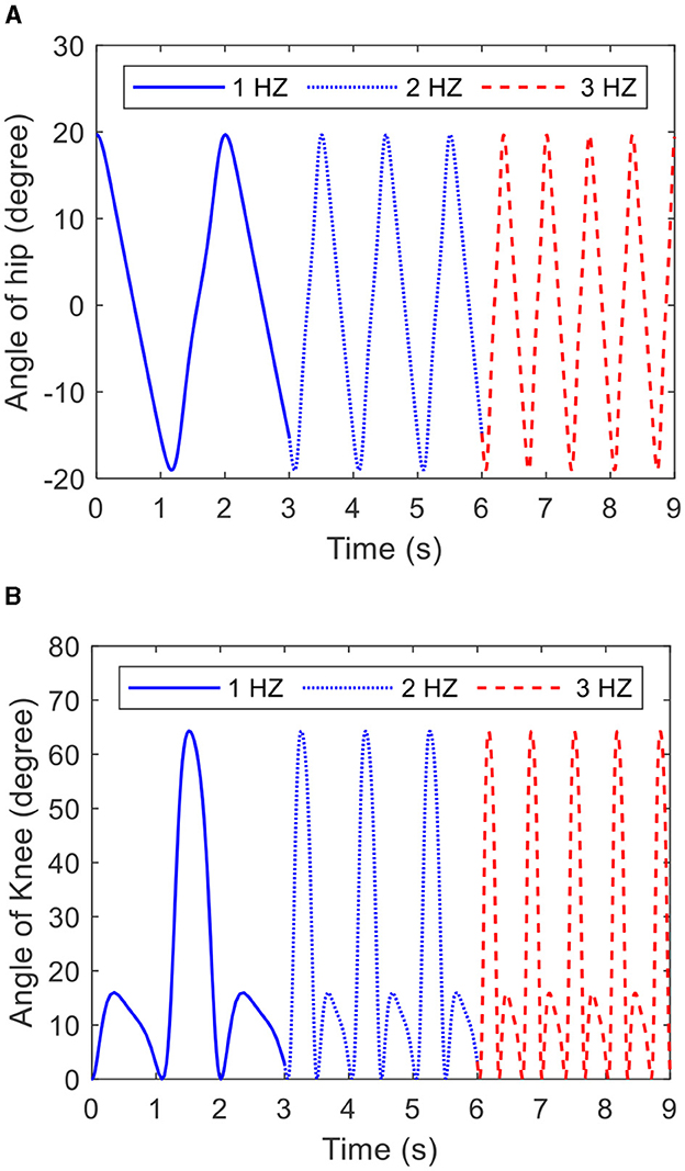
3.2.1 FrequencyAs Equation (27) shows, the frequency of the COCPG model is determined by ω. Figure 7 depicts the trajectories of the hip and knee joints generated by the COCPG model with ω of 1, 2, and 3 Hz, respectively. From Figure 7, it is obvious that the frequency of the COCPG model increases with increasing ω. Therefore, the frequency of the COCPG model is determined by the value of ω.
Figure 7. Trajectories of the joints of the lower limb generated by the COCPG model with different ω: (A) the hip joint and (B) the knee joint.
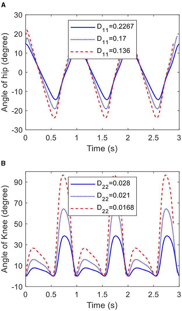
3.2.2 AmplitudeFrom Equation (27), it can be inferred that the angle amplitude of the hip joint of the COCPG model is only determined by D11, and the angle amplitude of the knee joint of the COCPG model is determined by D11 and D22. Figure 8 shows the trajectories of the joints of the lower limb generated by the COCPG model with different D11 and D22. Figure 8A shows the trajectories of the hip joint generated by the COCPG model when D11 is equal to 0.2267, 0.17, and 0.136, respectively. Figure 8B shows the trajectories of the knee joint generated by the model with D11 of 0.17 when D22 is equal to 0.028, 0.021, and 0.0168, respectively. From Figure 8, it is obvious that the amplitudes of the trajectories generated by the COCPG model decrease with increasing D11 and D22. Therefore, the trajectories of the joints of the lower limb with different amplitudes can be achieved by adjusting D11 and D22.
Figure 8. Trajectories of the hip and knee joints generated by the COCPG model with different D11 and D22: (A) the hip joint and (B) the knee joint.
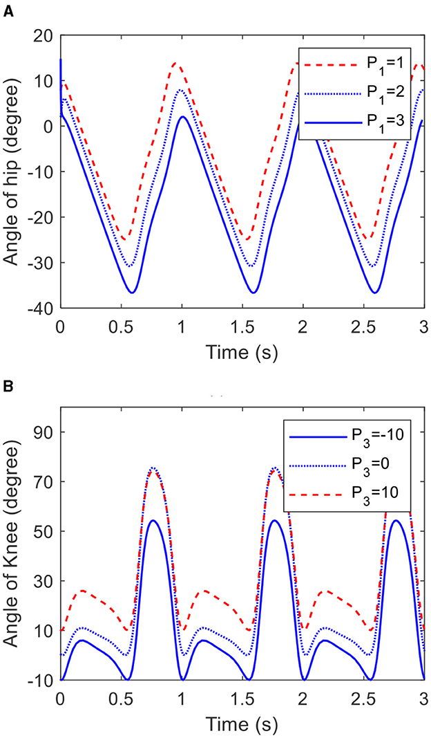
3.2.3 OffsetGoing by Equation (27), the offset of the trajectories generated by the COCPG model are determined by P1 and P3. Figure 9 shows the trajectories of the joints of the lower limb generated by the COCPG model with different P1 and P3, respectively. Figure 9A shows the trajectories of the hip joint generated by the COCPG model with P1 of 1, 2, and 3, and Figure 9B shows the trajectories of the knee joint generated by the COCPG model with P3 of −10, 0, and 10. It is clearly seen from Figure 9 that the offsets of the trajectories of the joints of the lower limb generated by the COCPG model increases along with the increase in the absolute value of P1 and P3.
Figure 9. Trajectories of the hip and knee joints generated by the COCPG model with different P1 and P3: (A) the hip joint and (B) the knee joint.
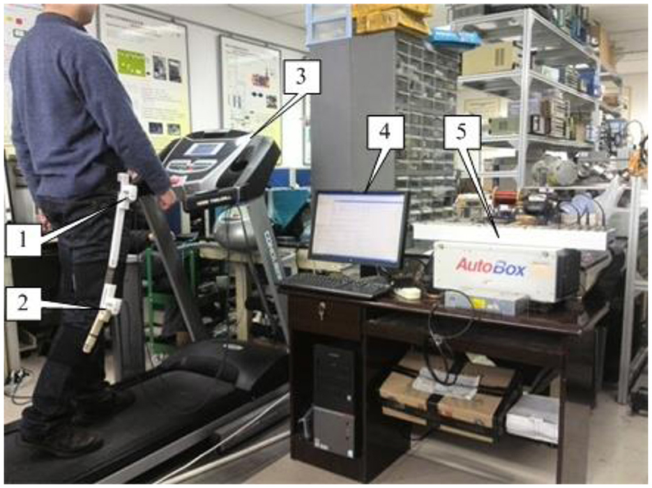
4 Experiments and results 4.1 Experimental setupIn order to evaluate the modeling accuracy of the COCPG model proposed in this article, the trajectories of the joints of the lower limb during walking are measured on an experimental setup, which is a test platform for prosthetic knees built by the authors (Wang et al., 2013). The test platform is presented in Figure 10. As shown in Figure 10, the experimental setup comprises a treadmill, two angle sensors, a data acquisition unit, and a tester. Two angle potentiometers, which are attached on the hip joint and the knee joint of the tester by three linkages, are used for measuring the angular displacements of the hip and knee joints. The host computer interrogates the voltage signals from the potentiometers via the data acquisition unit (type: DS1103, from the dSPACE GmbH, Germany) with a sampling frequency of 1 kHz.
Figure 10. Test platform updated from Wang et al. (2013) [1-angle sensor (AS3); 2-angle sensor (AS4); 3-treadmill; 4-PC; 5-dSPACE DS1103].
4.2 Results and analysisFigures 11A, B show the limit cycles and trajectories of the hip joint generated by the COCPG model (Equation 27) and measured from the tester on the test platform. For comparison, the limit cycle and trajectory of the hip joint generated by the CPG model based on the Rayleigh oscillator (ROCPG) are simultaneously provided. The Rayleigh oscillator is expressed as (de Pina Filho et al., 2005)
ÿ+d(l-ẏ2)ẋ+k2y=0 (28)where y is the output of the Rayleigh oscillator, d, l, and k are the parameters of the Rayleigh oscillator. In this article, the ROCPG model is based on Equation (28) with d = 0.14, l = 0.013, and k = 1.
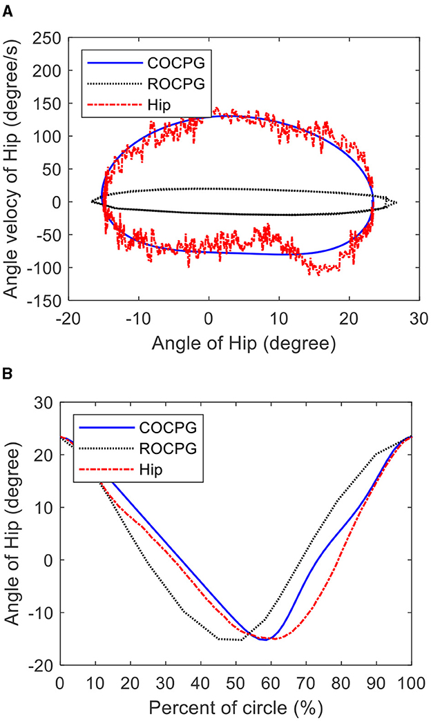
Figure 11. Hip motions measured from the tester on the test platform and generated by the COCPG model and the ROCPG model: (A) the limit cycles and (B) the trajectories.
Figure 11A shows that the limit cycle of the COCPG model is an asymmetric closed curve about its center, which is consistent with the measured limit cycle of the hip joint of the tester. However, the limit cycle of the ROCPG model is a symmetrical closed curve about its center, which differs from the measured limit cycle of the hip joint of the tester. Additionally, as shown in Figure 11B, the forward trajectory of the hip joint of the COCPG model accounts for 60% of one period and the forward progress of the hip joint generated by the ROCPG model accounts for 50%. Thus, the trajectory of the hip joint of the COCPG model is closer to that of the natural gait than that of the ROCPG model. Therefore, compared with the ROCPG model, the COCPG model is able to accurately imitate the rhythmic motions of the hip joints.
Figure 12 shows the differences between the measured trajectory of the hip joint of the tester and the trajectories of the hip joints generated by the COCPG and the ROCPG models. These differences can be defined as modeling errors. As shown in Figure 12, the maximum modeling error of the motion trajectory of the hip joint of the COCPG model is about 5°. Meanwhile, the maximum modeling error of the ROCPG model is about 15°, which is three times that of the COCPG model. The main source of the modeling error of the COCPG model is the flexible binding method of the measure unit. On the contrary, the main source of the modeling error of the ROCPG model is the asymmetry of the limit circle of the Rayleigh oscillator. As a result, the modeling accuracy of the output trajectories of the hip joint of the COCPG model is higher than that of the ROCPG model.
Figure 12. Differences between the measured trajectory of the hip joint of the tester and the trajectories of the hip joint of the COCPG model and the ROCPG model.
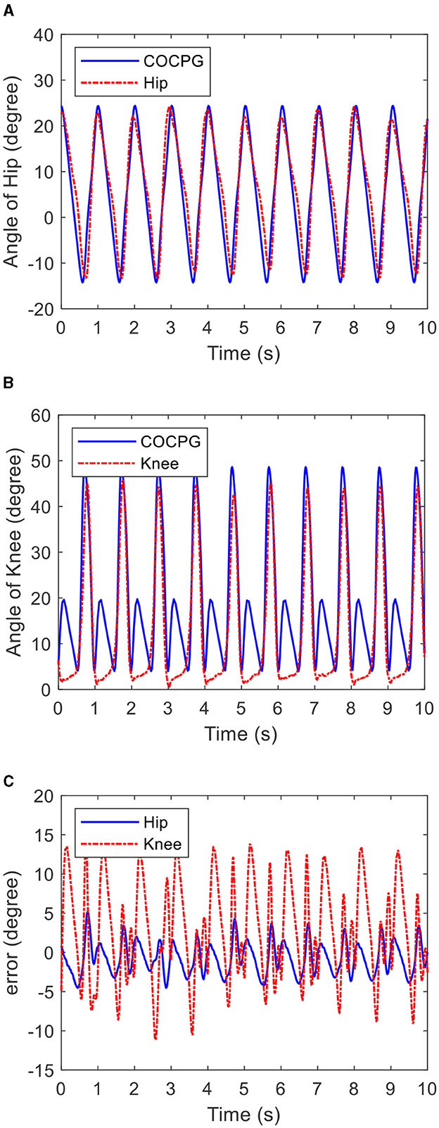
Figure 13 shows the time histories of the multi-periodic trajectories of the lower limb generated by the COCPG model and measured from the tester on the test platform. Figure 13A shows the trajectories of the hip joint and Figure 13B shows the trajectories of the knee joint. Figure 13C shows the differences between the measured trajectories of the tester and generated trajectories of the COCPG model. The maximum error between the hip joint trajectories and the models is 5°, while the maximum error between the knee joint trajectories and the models is 15°. The maximum error of the hip joint appears at the backward of the swing phase, and the maximum error of the knee joint appears at the stance phase. From Figure 13, it is clear that the trajectories of the COCPG model are consistent with those of the measured trajectories. Therefore, the COCPG model is suitable for imitating the rhythmic motions of the hip joint of the lower limb. However, the modeling error of the trajectory of the knee joint with the COCPG model still exists, which may be because the posture of the tester is deformed while walking on the treadmill and/or the angle potentiometers are not assembled on the sagittal plane.
Figure 13. Time histories of the multi-period trajectories of the lower limb generated by the COCPG model and measured from the tester on the test platform: (A) the trajectories of the hip joint, (B) the trajectories of the knee joint, and (C) differences between the measured trajectories of the tester and the COCPG model.
5 ConclusionsIn this article, to achieve the asymmetric time ratio of the trajectories of human hip joints and to simulate the coupling relationship between hip motions and knee motions, based on the CO with a central asymmetric limit cycle, the COCPG model for simulating asymmetric swing angles of lower limbs is proposed and developed. Based on the proposed method, the behaviors, such as frequency, amplitude, and offset, are analyzed by simulations. Additionally, in order to verify the accuracy of the COCPG model, experiments are conducted for comparing the outputs of the COCPG model with the measured trajectories from the tester on the test platform. The research results show that the trajectories of the hip joint generated by the COCPG model proposed in this article follow the asymmetric time ratio. The time ratios of the trajectories of the COCPG varied from 38 to 62%. Meanwhile, the time ration of the trajectories of the ROCPG are invariable. Compared with the ROCPG model, the COCPG model can imitate the hip motion with higher accuracy and the trajectories of the knee joint generated by the COCPG model is coupled with the hip motion. The maximum modeling error of the COCPG is 5°, which is introduced from the binding method of the measure unit. On the contrary, as a result of the symmetric limit circle, the maximum modeling error of the ROCPG increases to 15°. Moreover, the motion of the lower limb with different frequencies and amplitudes can be achieved by adjusting the parameters of the COCPG model. Therefore, the proposed pattern generator can be applied as the reference model for the lower limb exoskeleton controlling algorithm to produce the self-adjusted reference trajectories.
Although the proposed COCPG is an effective model for imitating the asymmetric and coupled behaviors of the lower limb, the coupling between the COCPG model and humans should be studied to promote its application in controlling a lower limb exoskeleton.
Data availability statementThe original contributions presented in the study are included in the article/supplementary material, further inquiries can be directed to the corresponding author.
Author contributionsQF: Writing – review & editing, Writing – original draft. TL: Writing – review & editing. TC: Writing – review & editing, Formal analysis, Data curation. XM: Writing – review & editing, Validation, Project administration. SL: Writing – review & editing, Resources, Formal analysis. YH: Writing – review & editing, Data curation, Conceptualization. SW: Writing – review & editing, Resources.
FundingThe author(s) declare financial support was received for the research, authorship, and/or publication of this article. This work has been supported by Scientific and Technological Research Program of Chongqing Science and Technology Bureau (Project No. cstc2020jcyj-msxm2322), National Natural Science Foundation of China (52175215), and Chongqing Talent Program Project (cstc2021ycjh-bgzxm0279), and Scientific and Technological Research Program of Chongqing University of Arts and Sciences (Project No. R2018JD03).
Conflict of interestThe authors declare that the research was conducted in the absence of any commercial or financial relationships that could be construed as a potential conflict of interest.
Publisher's noteAll claims expressed in this article are solely those of the authors and do not necessarily represent those of their affiliated organizations, or those of the publisher, the editors and the reviewers. Any product that may be evaluated in this article, or claim that may be made by its manufacturer, is not guaranteed or endorsed by the publisher.
ReferencesAcebrón, J. A., Bonilla, L. L., Pérez Vicente, C. J., Ritort, F., and Spigler, R. (2005). The Kuramoto model: a simple paradigm for synchronization phenomena. Rev. Mod. Phys. 77, 137–185. doi: 10.1103/RevModPhys.77.137
Crossref Full Text | Google Scholar
Conradt, J. (2003). “Distributed central pattern generator control for a serpentine robot,” in Proceedings of the International Conference on Artificial Neural Networks (Istanbul), 338–341.
de Pina Filho, A. C., Dutra, M. S., and Raptopoulos, L. S. C. (2005). Modeling of a bipedal robot using mutually coupled Rayleigh oscillators. Biol. Cybern. 92, 1–7. doi: 10.1007/s00422-004-0531-1
PubMed Abstract | Crossref Full Text | Google Scholar
Dingguo, Z., Yong, R., Kai, G., Jia, J., and Xu, W. (2017). Cooperative control for a hybrid rehabilitation system combining functional electrical stimulation and robotic exoskeleton. Front. Neurorobot. 11:725. doi: 10.3389/fnins.2017.00725
PubMed Abstract | Crossref Full Text | Google Scholar
Ekkachai, K., and Nilkhamhang, I. (2016). Swing phase control of semi-active prosthetic knee using neural network predictive control with particle swarm optimization. IEEE T. Neur. Sys. Reh. 24, 1169–1178. doi: 10.1109/TNSRE.2016.2521686
PubMed Abstract | Crossref Full Text | Google Scholar
Ferrario, A., Merrison-Hort, R., Soffe, S. R., Li, W. C., and Borisyuk, R. (2018). Bifurcations of limit cycles in a reduced model of the xenopus tadpole central pattern generator. J. Math. Neurosci. 8:9. doi: 10.1186/s13408-018-0065-9
PubMed Abstract | Crossref Full Text | Google Scholar
Fu, Q., Wang, D. H., Xu, L., and Yuan, G. (2017). A magnetorheological damper based prosthetic knee (MRPK) and sliding mode tracking control method for an MRPK-based lower-limb prosthesis. Smart Mater. Struct. 26:e045030. doi: 10.1088/1361-665X/aa61f1
Crossref Full Text | Google Scholar
Fu, Q., Wang, D. H., Xu, L., and Yuan, G. (2018). A cardioid oscillator with asymmetric time ratio for establishing CPG models. Biol. Cybern. 112, 227–235. doi: 10.1007/s00422-018-0746-1
PubMed Abstract | Crossref Full Text | Google Scholar
Glowinski, S., Krzyzynski, T., Bryndal, A., and Maciejewski, I. A. (2020). Kinematic model of a humanoid lower limb exoskeleton with hydraulic actuators. Sensors 20:6116. doi: 10.3390/s20216116
PubMed Abstract | Crossref Full Text | Google Scholar
Guo, X., Chen, L., Zhang, Y., Yang, P., and Zhang, L. (2010). “A study on control mechanism of above knee robotic prosthesis based on CPG model,” in Proceedings of the 2010 IEEE International Conference on Robotics and Biomimetics (ROBIO) (Tianjin), 283–287.
Katayama, S. I. (2012). Biomimetics micro robot with active hardware neural networks locomotion control and insect-like switching behaviour. Int. J. Adv. Robot. Syst. 9:54129. doi: 10.5772/54129
Crossref Full Text | Google Scholar
Ma, Y., Wu, X., Yang, S. X., Dang, C., Liu, D. X., Wang, C., et al. (2021). Online gait planning of lower-limb exoskeleton robot for paraplegic rehabilitation considering weight transfer process. IEEE T. Autom. Sci. Eng. 18, 414–425. doi: 10.1109/TASE.2020.2964807
Crossref Full Text | Google Scholar
Mokhtari, M., Taghizadeh, M., and Mazare, M. (2020). Hybrid adaptive robust control based on CPG and ZMP for a lower limb exoskeleton. Robotica 39, 182–199. doi: 10.1017/S0263574720000260
Crossref Full Text | Google Scholar
Mora, G., Torrealba, R. R., Cappelletto, J., Fermín, L., Fernández-López, G., and Grieco, J. C. (2012). Cybernetic knee prosthesis: application of an adaptive central pattern generator. Kybernetes 4, 192–205. doi: 10.1108/03684921211213034
Crossref Full Text | Google Scholar
Morimoto, J., Endo, G., Nakanishi, J., and Cheng, G. A. (2008). biologically inspired biped locomotion strategy for humanoid robots: modulation of sinusoidal patterns by a coupled oscillator model. IEEE T. Robot. 24, 185–191. doi: 10.1109/TRO.2008.915457
Crossref Full Text | Google Scholar
Nandi, G. C., Ijspeert, A. J., Chakraborty, P., and Nandi, A. (2009). Development of Adaptive Modular Active Leg (AMAL) using bipedal robotics technology. Robot. Auton. Syst. 57, 603–616. doi: 10.1016/j.robot.2009.02.002
留言 (0)