
記住我


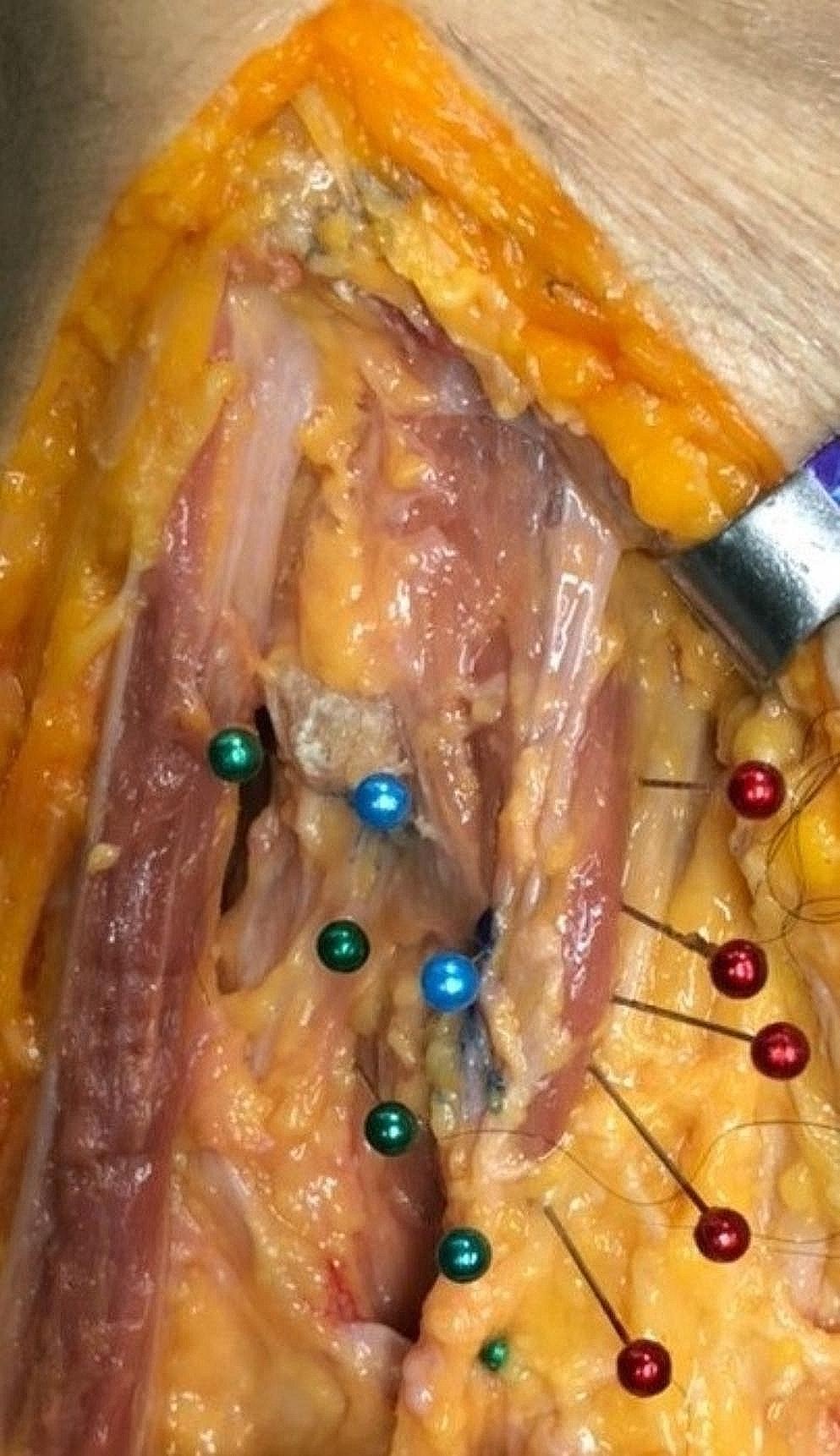

In all specimens, we were able to endoscopically expose the ACF and MCF from the nasopharynx to the PA, internal carotid artery (ICA), and the ITF space. After progressing into the nasal cavity, the inferior, middle, and superior conchae were visualized, and we focused on the area sits between the middle and inferior conchae (Fig. 2A-C). First, the sphenopalatine artery should be exposed. After isolating the sphenopalatine artery (lateralize or cauterize), the next step was removal of the lateral wall of the nasal cavity down to the level of the nasal floor (Fig. 2D-F). The mean width (superior-inferior) of the surgical corridor between the inferior and middle concha without concha resection was 10.1 ± 0.92 mm on the left and 10.56 ± 0.55 mm on the right, which shows the entry point of the ETETA and width of the surgical window. Also, the mean shortest distance from the nasal vestibule to the PT orifice was 76 ± 4.58 mm on the left and 75 ± 3.6 mm in the right nostril. The mean length of the PT was 41.7 ± 2.3 mm on the left and 42.7 ± 0.32 mm on the right side (Table 1). The sphenopalatine artery was located between the orbita and ethmoidal crest, anterior to the vidian nerve (VN) and pterygopalatine ganglion (Fig. 3). The mean direct distance from the ventral opening of the vidian canal (VC) to the left PT orifice was 22.9 ± 0.51 mm and 22.7 ± 0.65 mm on the left and right side, respectively (Table 1). After removing the periosteum of the posteromedial maxillary sinus wall, the distal segment of the internal maxillary artery (IMA) and its branches (ascending palatine artery, sphenopalatine artery) were identified (Fig. 4A). At the level of VN, with the vascular compartment of the pterygopalatine fossa (PPF) lateralized, the pterygopalatine ganglion, greater palatine nerve, lesser palatine nerve, infraorbital nerve, and maxillary nerve (V2) at the foramen rotundum (FR) were easily visualized and manipulated. It is critical to appreciate the distance of dissection to the FR to avoid neurovascular injury during drilling. We found the PPF was limited by the medial pterygoid muscles (MPM) posteriorly, the palatine bone anteromedially, and the maxilla anterolaterally (Fig. 4B). The VC was directed posteriorly toward the second genu of the ICA. Once the VC was exposed, the base of the pterygopalatine plates (PTPs) was identified immediately laterally. The VN was transected just proximal to its junction with the sphenopalatine ganglion to expose the lateral pterygoid plate (LPP) (Fig. 4A, B). The mean shortest distance from the ventral VC opening to the optic canal was 22.4 ± 0.9 mm on the left and 21.4 ± 0.55 mm on the right side (Table 1). Partial drilling of the pterygoid process around the VC in anterior-posterior direction created the window needed for accessing the deep target regions (ITF and PA). The IMA, V3, TVPM, LVPM, and PT can be exposed in front of the ITF. Foramen ovale (FO) and the mandibular nerve (V3) can be exposed with initial dissection of the lateral pterygoid muscle (LPM). V3 was an important landmark to locate the post-styloid compartment, as it was always just anterior to this space. The cartilaginous part of PT ran anteromedial to the FO. Dissection of the TVPM from the PT allowed the course of the PT to be observed without sacrificing the V3 (Fig. 4B, C).
Fig. 2
Endoscopic images of ETETA. (A) After advancing into the nasal cavity, the lower, middle, and upper turbinates were visualized. (B) PT between the middle and inferior turbinates was demonstrated. (C) Close-up of Fig. 2B. (D) In the endonasal procedure, the sphenopalatine artery should be exposed first. After the sphenopalatine artery was isolated, the lateral wall of the nasal cavity was resected. (E) The greater palatal artery and nerve were shown in the lateral wall of the nasal cavity. (F) The vidian nerve is shown within the vidian canal
Table 1 Morphometric measurements of Eustachian tube and its associated anatomical structures in the infratemporal fossaFig. 3
Endoscopic images of ETETA. (A) The course of the greater palatal artery and nerve and the sphenopalatine artery is shown. (B) Oblique view to Fig. 3A. (C) The sphenopalatine artery was retracted medially, showing the pterygopalatine ganglion. (D) The sphenopalatine artery was retracted laterally and the pterygopalatine ganglion and vidian nerve were revealed
Fig. 4
Endoscopic images of ETETA. (A) After periosteum removal of the diffuse adipose tissue around the posteromedial maxillary sinus wall and pterygopalatine fossa, the distal segment and branches of the maxillary artery (ascending palatine artery, sphenopalatine artery) were shown. (B) The region of PPF with MPMs posteriorly, palatine bone anteromedially, and maxilla anterolaterally is shown. (C) FO and V3 can be revealed by resection of the LPM. Resection of V3 may be necessary to expose the entire posterolateral portion of the PT. With ETETA, dissection of TVPM from PT allows observation of the course of PT without compromising V3. (D) After the TVPM and LVPM are resected, the cartilaginous laminae and PT are clearly exposed
The cartilaginous PT has a non-cartilaginous gap located inferolaterally between the medial and lateral cartilaginous laminae, which is covered by the tensor veli palatini muscle (TVPM), levator veli palatini muscle (LVPM), and the lateral fat pad. After removing the muscles and fat pad, the cartilaginous laminas and PT were exposed (Fig. 4D). The dissection was continued using the endoscope. The ITF was bounded superiorly by the floor of the MCF and anteriorly by the maxilla [5]. The pre-styloid compartment of ITF has a fat-containing space and is located between the MPM and TVPM. In addition, the ICA, internal jugular vein (IJV), and lower cranial nerves (IX through XII) are located in the post-styloid compartment (Fig. 5) [5].
Fig. 5
(A) Dissection stages were continued with endoscope guidance. PT was demonstrated anteromedial to PphICA. (B) Resection of the TVPM revealed the cartilaginous auditory tube lamina medialis and lateralis. (C) Resection of the LVPM yielded the anterolateral skull base attachment of the PT. (D) Oblique view to Fig. 5C.
Next, PT was observed anterior and medial to the parapharyngeal ICA (PphICA). Laterally translocating or resecting these neurovascular structures showed, in order, the MPM, TVPM, LVPM, and PT (Fig. 5A, B). MPM and the TVPM were closely related; therefore, complete separation is not always possible. Reaching the anterolateral skull base attachment of the PT was possible with resection of the TVPM from the anterolateral surface of the PT (Fig. 5A). PT was fully preserved to the PphICA, which was located between the styloid process and Rosenmüller’s fossa. The cartilaginous part of PT and torus tubarius (TT) inserted in the posterior border of the medial pterygoid process anteriorly (Fig. 5C, D) and the clivus and foramen lacerum (FL) posteriorly. From the TT, the cartilaginous PT extended posterosuperiorly until reaching its bony canal at the cranial base [14,15,16]. The TVPM and LVPM inserted in the anterior and inferior aspect of the cartilaginous PT. We found the PphICA was located at the junction of the bony and cartilaginous part of the PT, which corresponds to the most superior aspect of the insertion of the LVPM. The tensor tympani muscle (TTM) was located within a bony semicanal located superior and parallel to the semicanal of the PT (Fig. 5A and Fig. 4B). After drilling this area, the TTM anterior to the cartilaginous part of the PT was exposed. The TTM turns across the tympanic cavity and inserts into the medial margin of the handle of the malleus. The TVPM was located medial to the MPM and had both a bony insertion anterior to the carotid foramen and a cartilaginous insertion on the medial lamina of the cartilaginous PT. It originated from the scaphoid fossa, sphenoid spine, and lateral lamina of the cartilaginous PT, ran vertically down between the MPM and MPP and ended with the tendon winding around the pterygoid hamulus approximately parallel to the lumen of the PT.
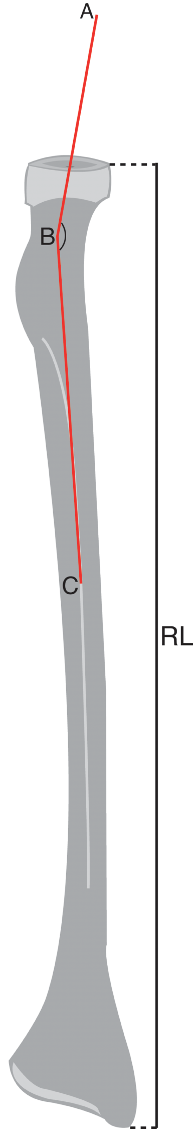
Next, the dissection was continued to expose the posterolateral, middle, and anteromedial parts of the PT. We found the posterolateral part was related to the greater wing of the sphenoid and PA, the middle part located above the FL, and the anteromedial part closely related to the pterygoid process. The mean of an obtuse angle between the midline and the left oblique line that is parallel to the PT trajectory and passes from pharyngeal PT orifice and tympanic orifice was 119.6 ± 3.81 and 119.8 ± 4.45 degrees on the left and right side, respectively (Table 1). PT ran from the PT sulcus to the nasopharynx through the scaphoid fossa and posteriorly, laterally, and superiorly from the nasopharynx to the middle ear and almost parallel to the horizontal segment of the internal carotid artery toward the pterygoid process. Removing the base of the pterygoid process exposed the pterygoid and scaphoid fossae, which contained the attachment of the MPM and TVPM. PT was not attached to these fossae and runs inferior to the scaphoid fossa. The venous plexus was found between the MPM and TVPM; however, less venous vascularity was found medial to the TVPM creating a plane that can be used to confirm the course of the PT (Fig. 6A, B). The TVPM was easily separated from the lateral surface of the PT. Lateralization of the TVPM clearly exposed the medial and lateral laminae of the cartilaginous tube and the LVPM. We found that the accessory meningeal artery passed superolateral to the TVPM and entered the skull base above the PT. We dissected the accessory meningeal artery to completely expose the attachment of the cartilaginous tube to the skull base. Bony dehiscence can often be observed on the medial wall of the osseous part of the PT that exposes the lateral wall of the ICA. The osseocartilaginous junction of the PT can be exposed from the superolateral direction, and the attachment of the LVPM was located just inferior to the junction. A fibrocartilaginous ring was then removed to facilitate the anterior translocation of the ICA, which allowed us to access and drill into the remaining PA. Infrapetrous approach to PA required the removal of the fibrocartilaginous tissue between the FL and PT to reach the anterior inferior PA. The ICA entered the cranial cavity through the carotid canal (CC) located in the petrous part of the temporal bone. The CC passed within the petrous bone, initially upward and then inward, and forward to the FL. Anterolateral to the carotid foramen there were two small canals, called the semicanal of the TTM and the semicanal of the PT, which passed under the tubal process of the tympanic part attached to the PA (Fig. 5A-C and Fig. 7). Anterior-medial to the semicanals, anterior and parallel to the horizontal segment of the CC, was the bony bed for the cartilaginous parts of the PT termed the PT sulcus. The anterior end of the PT sulcus was adjacent to the FL medially and scaphoid fossa laterally. At the FL, the PT and ICA were separated by fibrocartilaginous layers. Relevant radiologic measurements that were obtained on CT are shown in (Table 2).
Fig. 6
(A) The PT runs almost parallel to the pterygoid process from the PT sulcus to the nasopharynx through the scaphoid fossa and posteriorly, laterally, and superiorly from the nasopharynx to the middle ear and the horizontal segment of the internal carotid artery. Because there is less venous vascularity medial to the TVPM, this plane can be used to confirm the course of PT. (B) V3 and maxillary artery were resected to show the course of PT more clearly
Fig. 7
(A) Viewing the middle cranial fossa with a lateral (Subtemporal) approach; The petrous apex is shown in V3 and laterally. Osseous PT was demonstrated by extending the dissection laterally. (B) A zoomed view of the same dissection; TTM, GSPN, and PT were revealed in the middle cranial fossa. (C) Continuing the endoscope-guided dissection revealed osseous PT, V3 anterior to the TTM, and CN VII-VIII complex posteriorly within the internal acoustic canal. (D) Close-up oblique view of Fig. 7C. The relationship between PT and the CN VII tympanic segment was demonstrated
Table 2 Radiological parameters of Eustachian tube and its associated anatomical structures in the infratemporal fossa
留言 (0)