
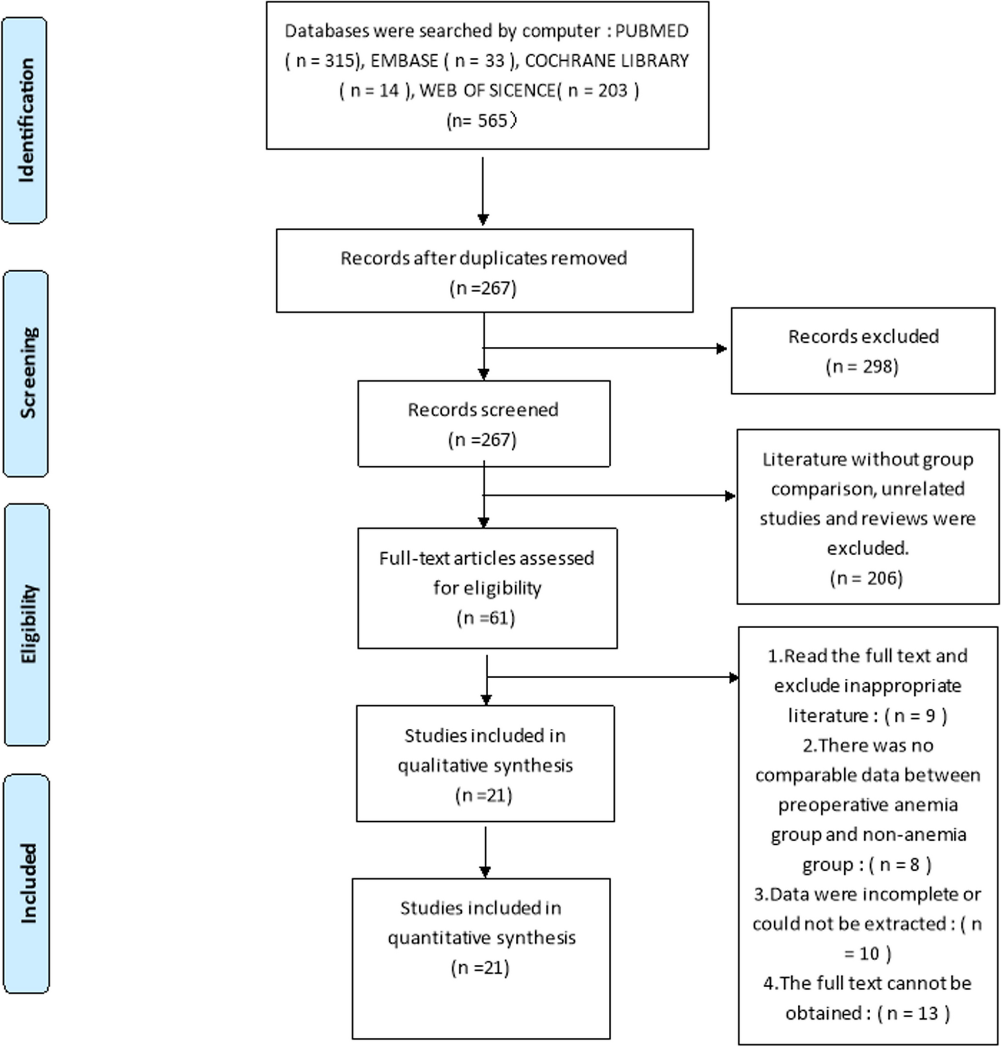
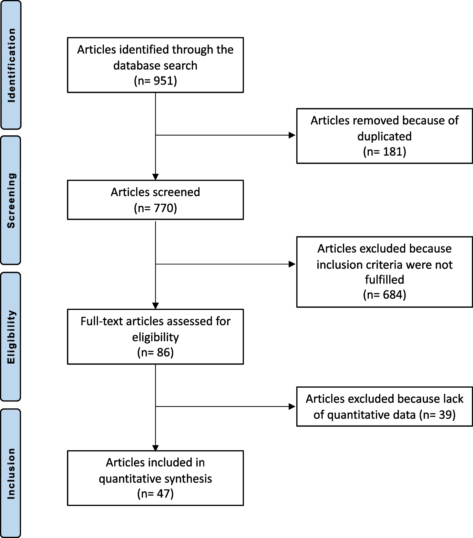
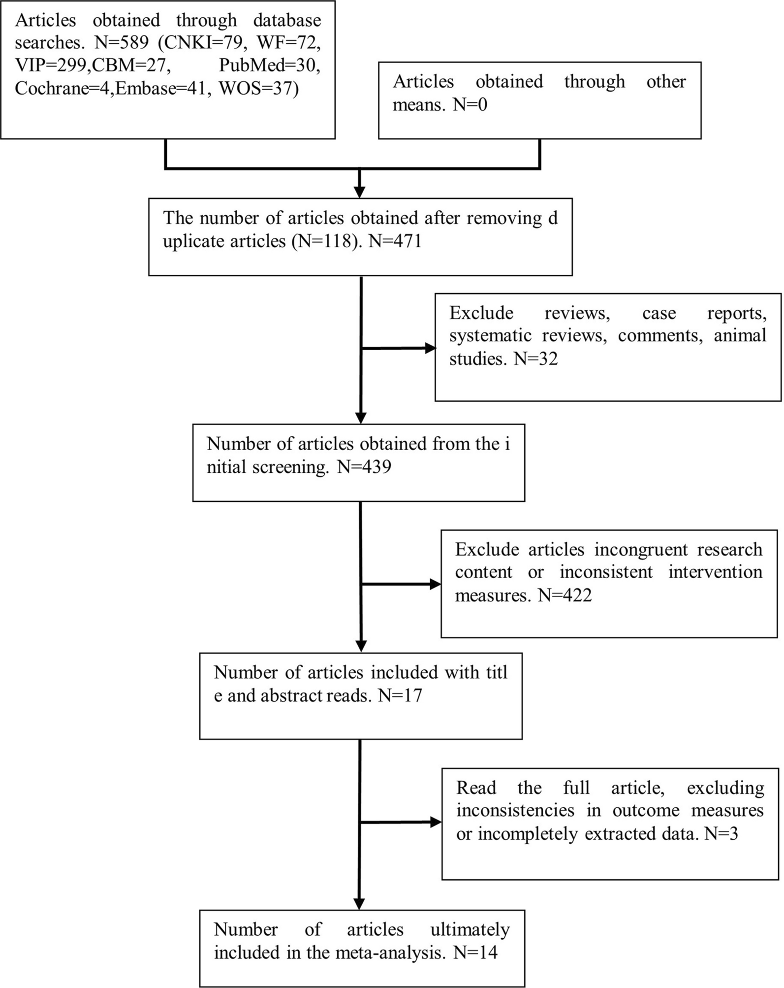
記住我


The Institutional Review Board of Khon Kaen University, Khon Kaen, Thailand, approved the study (HE641110). We first performed the finite element (FE) analysis of the femur, followed by the biomechanical study of the cadaveric femurs. For the results of an FE analysis to be credible, the model must be experimentally validated in at least one load case [14].
FE analysisThe DICOM format of the computed tomography (CT) scan of the fresh femoral cadaver was used to create the femoral models, which were then exported to MIMICS 10.01 (The Materialise, Leuven, Belgium). These models were then imported into SolidWorks 2015 software (SolidWorks Corp., MA, USA) and PowerShape 2013 (Autodesk Inc., San Rafael, California, USA). Stiffness analysis of the plate assembly was performed using ANSYS workbench 15.1 (ANSYS, Inc., Canonsburg, Pennsylvania, USA).
All the FE models were meshed using solid tetrahedral elements with ten nodes. The mesh of the bone model was refined with an element size of 4.0 mm. The model comprised the number of nodes and elements (924,099 and 593,835, respectively). The bones, implants, and bone cement material properties were assumed to be isotropic and linearly elastic. The Poisson’s ratio of the femur was 0.3 with a Young’s modulus of 0.805 GPa. The femur was 27.7 mm in diameter and 430 mm in length. The length of the 10-hole locking plates was 186 mm. The respective width and thickness of the locking plate were 17.5 and 6 mm. The screw was 4.5 mm in diameter and 33 mm in length. The locking plate and screws were stainless steel, element size 1 mm with a Young’s modulus of 200 GPa. The polymethylmethacrylate (PMMA) bone cement had a Young’s modulus of 2.7 GPa and a Poisson’s ratio of 0.35 [15]. The interface condition between the bone and plate was set as the contact condition, while the interface between the screw and the plate and the screw and the bone represented the bonded condition. The friction coefficient between the bone–cement interface was 0.3 [16].
Four FE models with a bone gap of 1 mm were created at the midshaft of the femur to simulate the host–graft junction [17, 18] (Fig. 1). The proximal part of the femur represented as the host bone, while the distal femur represented as the femoral allograft. In Model 1, the 10-hole locking plates were placed at the lateral and medial aspect of the femur. Model 2 was Model 1 with bone cement augmentation. Model 3 was the dual LP at the anterior and lateral aspect of the femur. Finally, Model 4 was Model 3 with bone cement augmentation.
Fig. 1
FE models of femurs with 10-hole dual LP configurations (P = posterior, L = lateral)
The femurs were tested for axial compression and torsional stiffness in the one-legged stance phase of walking with 15 degrees of adduction in the coronal plane and aligned vertically in the sagittal plane [19, 20] (Fig. 2A). A force of 1500 N was applied to the center of the femoral head to test for axial compression stiffness.
Fig. 2
FE model of the 10-hole dual LP during (A) the axial compression and torsional test and (B) the LM bending test
As for four-point bending stiffness, the femurs were positioned as shown in Fig. 2B, and a 1000-N force was applied in the lateral–medial (LM) and anterior–posterior (AP) direction to assess LM and AP bending stiffness, respectively.
As for torsional stiffness testing, the machine was set to torque at 12 N·m with a frequency of 0.1 Hz in three cycles. Then, the force was applied to the femoral head using angular displacement control (0.1 degrees/s) for both external and internal rotations.
The stiffness of each model was calculated by dividing the maximum force applied by the maximum deformation. The deformation (strain) measurements were recorded: between 10 and 1500 N as applied axially for axial compression testing; between 0.1 and 12 N·m for torsional testing; and between 10 and 1000 N for LM and AP bending.
Biomechanics testingThe fresh-frozen human cadaveric femur was obtained from the Department of Anatomy, Khon Kaen University. A 75-year-old man donor consented to using his body for research purposes. The femur was radiographed before the study to exclude fractures, infections, and bone tumors. All soft tissues were stripped from the bone. The femur was thawed at room temperature for 12 h before applying the plate and screws. An intramedullary canal was reamed 2 mm larger than the diameter of each femur. A reciprocating saw was used to make a 1-mm transverse osteotomy at midshaft of the femur to mimic the host–graft junction. Plastic cement plugs were inserted 95 mm from the osteotomy site at both the proximal and distal parts of the femur.
Polymethylmethacrylate (PMMA) bone cement (Rally®, medium viscosity with Gentamicin sulfate, Smith & Nephew, Inc., Memphis, TN, USA) was hand-mixed and left to cure at room temperature. The cement was poured into the medullary region of the femur, at both the proximal and distal segments. The cement was allowed to set for 20 min. The locking plates (4.5/5.0, broad Stainless-Steel Locking Compression Plate (LCP) System, DePuy Synthes Raynham, MA, USA) were applied laterally and anteriorly to the femurs according to standard surgical procedure. The femoral head and condyle were secured with multiple, custom, adjustable jigs to an Instron ElectroPuls™ E10000 Linear-Torsion (Illinois Tool Works Inc, MA, USA) (Fig. 3). Before biomechanical testing, the femurs were stored at room temperature for 6 h to allow cement curing. The axial compression, four-point bending, and torsional testing were performed three times to ensure reproducibility.
Fig. 3
Biomechanical testing for axial compression and torsional testing with the femur at 15 degrees of adduction in the coronal plane aligned vertically in the sagittal plane. The femoral head and condyle were secured to the Instron ElectroPuls ™ E10000 Linear-Torsion with custom, multiple, adjustable jigs
Axial compression testingIn order to simulate the single-leg stance phase of walking, an axial compression load of 1500 N was used with a preload of 50 N [19]. Finally, a maximum load of 1500 N was applied at 100 N/s. Bluehill 3 software was used to run all the tests.
Four-point bending testThe four-point bending test was done in two directions, LM and AP, to assess the respective LM and AP bending stiffness. The center of the machine was placed at the fracture site. A preload of 50 N was applied to a maximum of 1000 N at 100 N/s.
Torsional testingThe femur was positioned similarly for axial compression testing. A torque of 12 N·m at a frequency of 0.1 Hz was tested in both the internal and external rotations.
Statistical analysesThe Pearson’s correlation coefficient was used to compare the FE analysis results and the biomechanical testing. A p-value of less than 0.05 was considered statistically significant (SPSS version 23, SPSS Inc., Chicago, IL, USA).
留言 (0)