
記住我
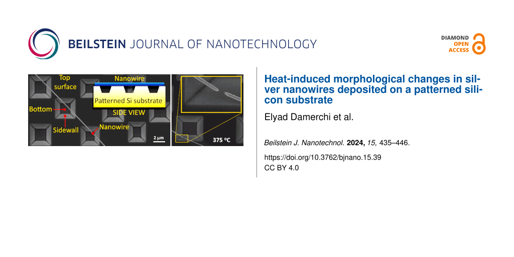

The catalysts under investigation were synthesized by electrodeposition onto the surface of nickel foam. The chronoamperometric graph recorded during the deposition is presented in Figure 1a.
![[2190-4286-14-34-1]](https://www.beilstein-journals.org/bjnano/content/figures/2190-4286-14-34-1.png?scale=2.0&max-width=1024&background=FFFFFF)
Figure 1: Chronoamperometric graphs recorded during electrochemical deposition of the catalysts on nickel foam (a), SEM images of GO (b), NiFe (c), CoNiFe (d), NiFe-GO (e), and CoNiFe-GO (f) deposited on nickel foam.
Each synthesis (except that of GO) began with a fast increase of the cathodic current, which is associated with the formation of the new catalyst phase on the surface of the substrate [25]. Afterwards, the current density tended to stabilize for NiFe and CoNiFe, which may be associated with the steady-state formation of the catalyst film on the metallic surface. The addition of cobalt to NiFe resulted in a lower overall current density during the synthesis process. In the case of the deposition of NiFe and CoNiFe on GO/nickel foam, the specific current density peak appeared after around 8 s and 20 s of the deposition for CoNiFe-GO and NiFe-GO, respectively. Because the metallic films were deposited on the surface of nickel foam already modified with GO, the peak may be associated with the reduction process of the already deposited GO. Afterwards, the current density increased due to the film formation, and then it gradually stabilized over time. A different chronoamperometric trend can be observed in the case of the electrodeposition of GO on the surface of nickel foam (Figure 1a inset). In this case, the cathodic current density decreased during the first 6 s of the synthesis, then it increased and tended to stabilize. The initial drop of the current density may be related to the preparation (e.g., passivation) of the metallic surface for GO deposition. The latter is a typical process in the electrodeposition of conductive films on active metals [26].
The morphology of the deposits was analyzed by scanning electron microscopy (SEM) and is presented in Figure 1b–f. Typical GO flakes regularly distributed over the surface of the nickel foam were successfully obtained after the one-step electrodeposition process (Figure 1b). The structure of the NiFe deposited directly on the substrate was characterized by the nanoflake-like morphology that is common for electrodeposited NiFe (oxy)hydroxides/oxides LDH [27]. The structure of the NiFe after the addition of cobalt (CoNiFe) was characterized by interconnected nanoflakes, which formed a porous 3D structure uniformly distributed over the entire surface of the nickel foam (Figure 1d). The morphology of the catalysts changed after the combination of GO with NiFe and CoNiFe (Figure 1e,f). In each case, the SEM images clearly show the complete coverage of the surface of the GO/Ni foam with the NiFe or CoNiFe. Less nanoplate-like structures of NiFe could be observed around the GO flakes (Figure 1e). The already deposited GO probably inhibited the formation of Ni and Fe species on its surface. Nevertheless, the morphology of NiFe and GO (Figure 1e) is similar to that observed for each of the singly deposited materials (Figure 1b for GO, Figure 1c for NiFe). Different morphologies can be observed in the case of CoNiFe (Figure 1d) and CoNiFe-GO (Figure 1f). Here, the addition of the GO layer induced much more differences in the morphology of the deposits. Deposition of CoNiFe on the GO/Ni foam changed the shape of the GO flakes, with some visible agglomerations (Figure 1f). In contrast, the presence of GO resulted in the formation of a CoNiFe layer, which only remained an interconnected 3D porous material in some areas. Additional SEM images with different magnifications of the morphology of NiFe and CoNiFe after GO addition are presented in Figure S1 and S2, respectively, in Supporting Information File 1.
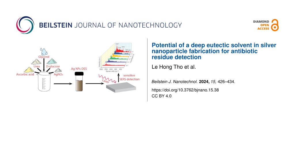
Figure 2 presents the energy-dispersive X-ray (EDX) maps with corresponding SEM images of the catalysts. The analysis confirms the presence of the following elements in the catalyst structure: Ni and Fe for NiFe and NiFe-GO, and Ni, Fe, and Co for CoNiFe and CoNiFe-GO. A high amount of detected nickel is due to the presence of nickel in the catalyst but also in the nickel substrate. Since an extremely low atom % fraction of iron in NiFe-GO was detected, additional EDX graphs confirming the presence of this element in the catalyst structure has been provided in Supporting Information File 1 (Figure S3). The EDX maps show that then deposition of nickel, iron, and cobalt species is preferable on the surface around the graphene oxide flake. The deposited GO probably inhibited the electrodeposition process of NiFe and CoNiFe on its surface. This may be the reason for the slower stabilization of the synthesis current density observed in the chronoamperograms (Figure 1a).
![[2190-4286-14-34-2]](https://www.beilstein-journals.org/bjnano/content/figures/2190-4286-14-34-2.png?scale=2.0&max-width=1024&background=FFFFFF)
Figure 2: SEM images and corresponding EDX maps of NiFe (a), NiFe-GO (b), CoNiFe (c), and CoNiFe-GO (d) deposited on nickel foam (error ≤ 0.5 atom %).
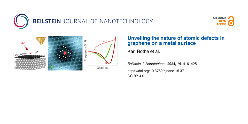
X-ray diffraction, X-ray photoemission spectroscopy and X-ray absorption spectroscopyFigure 3a–d shows the X-ray absorption spectra (XAS) of the L3 edge of nickel (a), iron (b), cobalt (c), and carbon (d) in the studied catalysts.
![[2190-4286-14-34-3]](https://www.beilstein-journals.org/bjnano/content/figures/2190-4286-14-34-3.png?scale=2.0&max-width=1024&background=FFFFFF)
Figure 3: Normalized XAS spectra (a–d) and XRD patterns (e) of NiFe, CoNiFe, NiFe-GO, and CoNiFe-GO.
The appearance of a shoulder peak at the L3 edge of the nickel (Figure 3a) at 855 eV indicates the presence of oxides in the structure of the catalysts (Ni in a strong crystal field) [28,29]. The shape of the XAS spectra (Ni edge) indicates a similar type of oxides in the structure of the catalysts. The addition of GO to NiFe and CoNiFe intensified both the nickel and iron L3 edge peaks, indicating partial electron transfer from nickel and iron to the substitutional GO (carbon) [30]. In the case of the edge of iron (Figure 3b), the XAS spectra indicate the presence of iron atoms in the oxidation state Fe3+ in each of the studied catalysts [28,29]. The iron edge peak observed at 707 eV disappeared after the addition of GO to CoNiFe, indicating a change in the structure of the catalyst. However, the type of oxides/hydroxides present in the catalyst structure cannot be determined from the spectra.
A shift of the XAS spectrum and a change in its intensity were observed for the L3 edge of cobalt after addition of GO into CoNiFe (Figure 3c). The observed changes indicate charge transfer from cobalt to carbon and the formation of Co–O–C bonds in the catalyst [31]. Moreover, the spectra show that the dominant cobalt species in the studied catalysts were Co3+ and Co2+[25].
The L3 edge of carbon in NiFe-GO and CoNiFe-GO is presented in Figure 3d. In general, the absorption edges at 285.2 and 293.7 eV correspond to the excitation of electrons in the sp2 network into the π* band (C=C) and σ* band (C–C), respectively [32,33]. The signals observed at 287.2 eV (σ*: C–O and/or π*: C–OH), 288.4 eV (σ*: C–O), 290.1 eV (π*: C=O) and 291.6 eV (π*: O–C=O) correspond to a state in which the local sp2 bonding is influenced mainly by oxygen functionalization [32,33]. The position of the peak and the intensity of the spectra differ for NiFe-GO and CoNiFe-GO, indicating different electronic structures and interactions around Ni, Fe, Co, and GO.
Figure 3e presents the XRD pattern of the samples. The reflections of nickel hydroxide were detected at 2θ of around 10.8° and 22.5° (following the JCDS database (38–715)), for NiFe-GO, CoNiFe-GO, CoNiFe, and CoNiFe-GO, respectively, confirming a typical pattern of layered double hydroxides (LDHs) [34]. The analysis showed that the addition of GO into both NiFe and CoNiFe induced the formation of a nickel hydroxide LDH, which was observed in the XRD spectra as the appearance of more intense nickel LDH reflections. No LDH reflections were detected for NiFe, which can be related either to the absence of a LDH structure or a too faint XRD signal due to the very thin NiFe layer (200 nm).
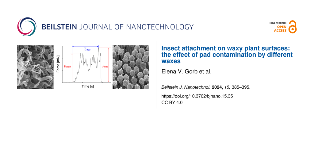
The XPS analysis showed that the addition of cobalt to NiFe induced the formation of the new nickel species Ni3+ in the catalyst structure (Figure 4a). The effect of the addition of cobalt to the NiFe on its structure was studied in detail in our previous work [25]. The appearance of Ni3+ was also observed after the addition of GO to NiFe. Both, GO and the addition of Co to NiFe resulted in the formation of nickel species in the oxidation states Ni2+ and Ni3+ with the same Ni2+/Ni3+ ratio of around 80%/20%. The addition of GO to CoNiFe did not change the structure of the catalyst concerning the type of the nickel species and the ratio of Ni2+/Ni3+ (80%/20%).
![[2190-4286-14-34-4]](https://www.beilstein-journals.org/bjnano/content/figures/2190-4286-14-34-4.png?scale=2.0&max-width=1024&background=FFFFFF)
Figure 4: XPS high-resolution spectra of Ni 2p (a), Fe 2p (b), Co 2p (c), and C 1s (d) levels of the catalysts with the determined surface concentration of the elements (error ≤ 5%).
Two kinds of iron species were found in each of the materials studied, namely Fe2+ and Fe3+ (Figure 4b). The Fe2+/Fe3+ ratio in NiFe slightly decreased from 45%/55% to 39%/61% after the addition of cobalt. A different situation was observed in the case of the NiFe and CoNiFe catalysts after the addition of GO. The ratio of Fe2+/Fe3+ increased from Fe2+(45%)/Fe3+(55%) to Fe2+(57%)/Fe3+(43%) for NiFe, and from Fe2+(39%)/Fe3+(61%) to Fe2+(46%)/Fe3+(54%) for CoNiFe. The same type of cobalt species, that is, Co2+ and Co3+, and virtually the same percentage ratio of Co2+/Co3+ remained in the catalyst after the addition of GO to CoNiFe (Figure 4c).
Figure 4d presents the XPS spectra of the C 1s region of GO, NiFe-GO, and CoNiFe-GO. The C 1s spectrum of the catalysts indicates the degree of oxidation with four different components corresponding to carbon atoms in different functional groups, that is, non-oxygenated ring C–C (284.9 eV), the C in C–O (286.6 eV) and C=O (288.5 eV) bonds, and carboxylate carbon O–C=O (290.0 eV), which agrees with the XAS analysis (Figure 3) [35]. The analysis showed that the fraction of non-oxygenated ring C is about 37% for GO, while it increased significantly after combining GO with NiFe (81%) or CoNiFe (84%). The percentage of C–O, C=O, and O–C=O decreased down to around 5–7%, 9–13%, and 1–2%, respectively, for the GO-modified catalysts. The latter indicates that most of the oxygen functional groups in GO were removed, and thus the GO present in the structure of the NiFe or CoNiFe is in a reduced form [20]. The analysis confirms that the second step of the electrodeposition process leads to the simultaneous deposition of NiFe or CoNiFe and the reduction of the GO. A reduced form of GO combined with NiFe was also obtained by others after one-step electrodeposition by cyclic voltammetry [12].
Electrochemical studies of the catalysts towards the OERThe electrochemical performance of the catalysts towards the OER was studied in an aqueous solution of 1 M KOH. Figure 5 presents the LSV graphs (Figure 5a) with the corresponding evolutions of OER overpotential (determined at 10 mA·cm−2), onset potential Eonset (Figure 5b), and Tafel plots (Figure 5c).
![[2190-4286-14-34-5]](https://www.beilstein-journals.org/bjnano/content/figures/2190-4286-14-34-5.png?scale=2.0&max-width=1024&background=FFFFFF)
Figure 5: Linear scan voltammetry profiles (a) with corresponding evolutions of the OER overpotential η (10 mA·cm−2) and onset potential Eonset (b), and Tafel plots (c) of the catalysts. Double layer capacitance Cdl (d) and corresponding electrochemical active surface area (ECSA) (e) determined for each catalyst.
The LSV graphs and the corresponding evolutions of the OER overpotential and the onset potential Eonset show that coating the nickel foam with the catalyst layer resulted in each case in a higher catalytic performance of the sample towards the OER compared to the bare substrate. The addition of GO to NiFe significantly reduced η (10 mA·cm−2) and Eonset to 210 mV and 1.34 V, respectively, compared to GO (η: 320 mV, Eonset: 1.52 V) and NiFe (η: 235 mV, Eonset: 1.44 V) alone. A difference was observed in the case of the CoNiFe and CoNiFe-GO catalysts. Here, the addition of GO to CoNiFe (η: 230 mV, Eonset: 1.44 V) significantly increased the OER catalytic activity of the sample compared to GO alone (η: 320 mV, Eonset: 1.52 V), but the overall activity of the CoNiFe-GO was lowered compared to CoNiFe alone (η: 224 mV, Eonset: 1.41 V).
The catalytic efficiency towards the OER can be also assessed by analyzing the Tafel plots of the catalysts (Figure 5c). The Tafel slope for bare nickel foam was determined to be 99 mV·dec−1, which is in agreement with the literature [36,37]. A lower Tafel slope was observed for nickel coated with GO, indicating faster kinetics towards the OER compared to the bare substrate [38]. The slopes for NiFe (41 mV·dec−1) and CoNiFe (42 mV·dec−1) were similar, which indicates that the same OER catalytic mechanism was in action. The addition of GO to NiFe resulted in a slight increase of the slope from 41 to 46 mV·dec−1, while the presence of GO in CoNiFe led to a decrease in Tafel slope down to 33 mV·dec−1.
Figure 5d and Figure 5e present a linear approximation of the capacitive currents as a function of the scan rate obtained from cyclic voltammograms with the determined double layer capacitance Cdl and the corresponding ECSA, respectively, for the samples. Coating the nickel foam with the catalysts resulted in each case in an increase of Cdl/ECSA compared to the bare substrate. The highest value of Cdl/ECSA was obtained for CoNiFe. The addition of cobalt to NiFe resulted in a nearly fourfold increase in the surface area of the catalyst. The latter was related to the change in morphology from the nanoplate-like structure typical for NiFe to the porous interconnected 3D nanoplate network typical for CoNiFe (Figure 1). The increase in the surface area of the catalyst after mild doping of NiFe with cobalt has also been described in the literature [39]. The addition of GO to CoNiFe left the value of Cdl/ECSA of the material virtually unchanged (slightly lowered) compared to CoNiFe alone. A difference could be observed in the case of GO and NiFe. Here, the surface area of NiFe increased after adding GO to its structure. The value of Cdl/ECSA of GO (3.2 mF·cm−2geo/20 cm2) is higher than that of NiFe (2.5 mF·cm−2geo/15.5 cm2) alone, which indicates that GO is responsible for the increase in the surface area of the NiFe-GO (4.0 mF·cm−2geo/25.0 cm2). The virtual lack of change in the CoNiFe-GO surface area and the change of the surface in the NiFe-GO sample compared to the catalysts alone may be due to the change in morphology observed in the SEM images (Figure 1).
Since NiFe-GO revealed a higher catalytic activity towards the OER than NiFe and GO alone and the other catalysts, further electrochemical studies focused on this material. Figure 6 and Figure 7 present the effect of the change in the electrodeposition charge Qdep of NiFe in NiFe-GO and GO in NiFe-GO, respectively, on their electrocatalytic performance towards the OER and on the value of Cdl/ECSA. The LSV profiles of NiFe (Qdep: 50–200 mC)-GO recorded in an aqueous solution of 1 M KOH and the corresponding evolution of the OER overpotentials are presented in Figure 6a and Figure 6c, respectively. The graphs clearly show that the OER overpotential decreases with a higher deposition charge of NiFe, which is valid for Qdep ≤ 200 mC. The lowest η(10 mA·cm−2), equaling 210 mV, was obtained for NiFe(200 mC)-GO, while the highest η(10 mA·cm−2) of 250 mV was obtained for NiFe(50 mC)-GO. The corresponding Tafel slopes reveal a similar trend as the OER η: the higher Qdep of NiFe in NiFe-GO, the lower the slope (valid for Qdep < 200 mC). Any change or deterioration of the OER catalytic activity of NiFe-GO for Qdep > 200 mC may be due to the overgrow of deposited NiFe, which begins to block the ion and electron transport. The latter can also be confirmed by the Tafel slope analysis. The slopes for NiFe(300 mC)-GO begin to rise quickly, which indicates a change in the OER kinetics due to the slowed exchange of ions and electrons. The connection of GO with NiFe resulted in a slight increase of the value of Cdl/ECSA compared to the GO and NiFe alone (Figure 5d,e). However, Figure 6d shows that this change is further independent on the NiFe deposition charge. A difference was observed for GO in NiFe-GO (Figure 7). The OER η of NiFe-GO(100–300 mC) decreased as the Qdep of GO increased, which was valid for Qdep ≤ 200 mC. A higher deposition charge of GO in NiFe-GO resulted in a re-increase of the OER η up to 233 mV, which was due to the overgrowth of GO over NiFe, characterized by a significantly higher value of Cdl/ECSA of 7.0 mF·cm−2/44.0 cm2 compared to the rest of the samples.
![[2190-4286-14-34-6]](https://www.beilstein-journals.org/bjnano/content/figures/2190-4286-14-34-6.png?scale=2.0&max-width=1024&background=FFFFFF)
Figure 6: Linear scan voltammetry profiles (a) with corresponding Tafel plots (b) and evolution of the OER overpotential η(10 mA·cm−2) (c), and values of Cdl and ECSA (d) of the catalysts.
![[2190-4286-14-34-7]](https://www.beilstein-journals.org/bjnano/content/figures/2190-4286-14-34-7.png?scale=2.0&max-width=1024&background=FFFFFF)
Figure 7: Linear scan voltammetry profiles (a) with corresponding Tafel plots (b) and evolution of the OER overpotential η (±3 mV) (c), and values of Cdl and ECSA (d) of the catalysts.
This, in turn, resulted in blocking of the catalyst surface and the ion and electron transport became inhibited. The value of Cdl/ECSA for NiFe-GO(100–300 mC) progressively increased as the deposition charge of GO in NiFe-GO increased, which was a different trend compared to NiFe(50–300 mC)-GO. Because of this, the data indicate that the improvement in the OER of NiFe-GO with the higher Qdep of NiFe and GO resulted mainly from the NiFe structure and the electroactive surface area and the porosity of GO.
Electrochemical impedance spectroscopy (EIS) was performed in order to determine the charge transfer resistance (Rct) of the specific catalysts. The EIS spectra are presented in Supporting Information File 1 (Figure S4). Rct values of 0.43, 0.50, 0.57, and 0.65 Ω were determined for NiFe-GO, CoNiFe, CoNiFe-GO, and NiFe, respectively. A decrease in Rct is associated with more efficient reaction rates for the OER. The EIS results are in agreement with the trend of the evolution of η and Eonset determined based on LSV (Figure 5a,b).
The stability test of the most promising among studied catalysts was assessed during chronoamperometry measurements at 10 mA∙cm−2geo (Figure 8a).
![[2190-4286-14-34-8]](https://www.beilstein-journals.org/bjnano/content/figures/2190-4286-14-34-8.png?scale=2.0&max-width=1024&background=FFFFFF)
Figure 8: Chronopotentiometric curves recorded in aqueous solution of 1 M KOH at 10 mA∙cm−2geo (a) and SEM images after the test of NiFe (b), CoNiFe (c), NiFe-GO (d), and CoNiFe-GO (e).
A rapid increase of the potential at the beginning of the test was observed for each of the studied catalysts. This was due to the reduction of the catalysts’ active surface area through the physical absorption of the generated oxygen bubbles on the electrode surface, which was also observed by others [40]. The recorded potential deviated in a range of 1.46–1.48 V for NiFe, 1.46–1.47 V for CoNiFe, 1.44–1.46 V for NiFe-GO, and 1.44–1.45 V for CoNiFe-GO for the measurement period from t0h to t22h. In each case, the presence of GO in the structure resulted in a lower working potential for the entire duration of the measurement compared to the catalysts without GO. Moreover, it can be also observed that the addition of cobalt in the structure of the catalysts resulted in a slightly lower potential deviation during the measurement from t0h to t22h. The morphology of the catalysts after the test changed slightly in each case (Figure 8b–e). The plate-like structure remained for NiFe and CoNiFe catalysts. However, in each case, some material agglomeration occurred randomly on the surface of the electrodes. No detachment of the catalyst from the surface of the nickel foam was observed.
留言 (0)