
記住我


Undoubtedly, robots are becoming intimate and ubiquitous in our lives. Interactive robotics research and innovation is a megatrend in the new era of robotics. Collaborative robots (cobots), which are supposed to be deployed and work in the proximity of humans, have already demonstrated high potential in manufacturing systems (Djuric et al., 2016), construction sites (Liu et al., 2021) and even human-inhabited environments such as hospitals (Vogel et al., 2020b) and age- or disabled-appropriate houses (Vogel et al., 2020a). It is well recognized that cobots are indispensable elements in future factories as they can bring high flexibility and adaptability to the industrial processes for flexible and agile manufacturing as a featured trend in Industry 4.0 (Shi et al., 2012), and they can also contribute to improving the quality of people's daily life (Veloso et al., 2015).
Physical Human-Robot Collaboration (PHRC) is a special type of physical human-robot interaction, and it is defined when human(s), cobot(s) and the environment come to intentional and continuous contact(s) with each other and form a coupled dynamic system to accomplish a task (Bauer et al., 2008; Krüger et al., 2009). Future generation of cobots are envisioned to get closer to humans and can realize PHRC tasks in more challenging applications by tightly combining cobot physical capability and human cognitive ability. For instance, when a human worker and a cobot co-manipulate a car engine and transport it to a target place, the cobot can take most of the payload while the human worker can lead the engine to the target place and perform fine adjustment of the engine's position and orientation for further accurate operations, e.g., assembly. This is a typical scenario where PHRC is necessarily required. Similar scenarios can be easily found wherever fine manipulation of bulky and/or heavy objects is required, e.g., in healthcare (co-transporting patients), construction (co-assembly), logistics (co-transportation) domains, among others.
Research in PHRC has been active and popular in academia, and relevant progress and advances have been made in many aspects including control schemes, interaction modalities and interfaces for improved human and robot perception (Ajoudani et al., 2018b). To turn these research investigations into trustworthy technologies, which can make impact in real-world applications, safety is of paramount importance for the deployment of PHRC systems (Gualtieri et al., 2021). A large body of research work has been conducted on safety issues concerning unintentional collisions between human and cobot. Seven sequential phases of a collision event have been recognized and studied in literature including Pre-Collision (Khatib, 1985), Collision Detection (Suita et al., 1995), Collision Isolation (Yamada et al., 1997), Collision Identification (De Luca and Mattone, 2005), Collision Classification (Golz et al., 2015), Collision Reaction (Haddadin et al., 2008) and Post-Collision (Parusel et al., 2011), and they have been systematically summarized within a single safety framework in Haddadin et al. (2017), and some of them have been implemented as an open-source library, OpenPHRI (Navarro et al., 2017). This framework is, however, a collision-based safety framework in physical human-robot interaction where the goal is to avoid unintentional contacts/collisions. In contrast, the role of contact is rethought in PHRC, and intentional contacts are actively utilized to connect the human and the robot to form a powerful collaborative system and achieve cohesive synergy. But safety study of PHRC has been rarely touched and a PHRC safety framework is completely missing (Bi et al., 2021). Consequently, PHRC has been discussed extensively in academia, but rarely seen in industries. A key reason for the lack of systematic safety research is real PHRC experiments (usually many trials) regarding safety evaluation are typically dangerous, cumbersome and inconvenient.
On the other hand, ergonomics research in PHRC is recently emerging (Gualtieri et al., 2021). Ergonomics in PHRC is concerned with chronic health risks or illness incurred by inappropriate repetitive interactions between humans and cobots in static or quasi-static scenarios (e.g., human-robot co-assembly and co-drilling) while safety in PHRC is associated with instant physical injuries caused by more dynamic interactions (e.g., human-robot co-lifting and co-transportation). A collaborative cell was developed to improve the operator ergonomics during human-robot co-assembly tasks (Cherubini et al., 2016). A fatigue management framework in PHRC tasks was proposed by utilizing the human muscle force estimation based on a musculoskeletal model (Peternel et al., 2018). A reconfigurable human-robot collaboration workstation was developed to improve the worker ergonomics and productivity during co-manipulation tasks (Kim et al., 2019). A digital human model was used to simulate PHRC tasks for improving the design of cobots in terms of human ergonomics in Maurice et al. (2017) where a co-drilling task was demonstrated for the process of cobot design optimization. The ergonomics assessment and intervention are usually conducted either on real systems in real time, where preparing and setting up the whole system is time-consuming, or in pure simulations where the accuracy of the human model and its reactive behavior are questionable.
A big obstacle to the development of safety and ergonomics research in PHRC is the lack of a general platform for assessing the safety and ergonomics of PHRC tasks. This paper is targeted at this issue, and the contribution lies in the creation of a PHRC physical emulator, PREDICTOR, as a new tool enabling the safety and ergonomics evaluation of PHRC. PREDICTOR combines haptics and Virtual Reality (VR) to enable physical interaction between real human operator and virtual cobot through virtual co-manipulated object in PHRC. Real human operator is involved instead of digital human model for real reactive behavior and dangerous heavy/bulky object and robot are simulated for safety reason, which are the main benefits of PREDICTOR. It can predict what will happen in a real counterpart in order to optimize the control schemes and/or tasks, and train human operators before real PHRC experiments.
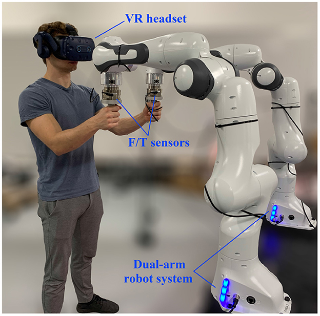
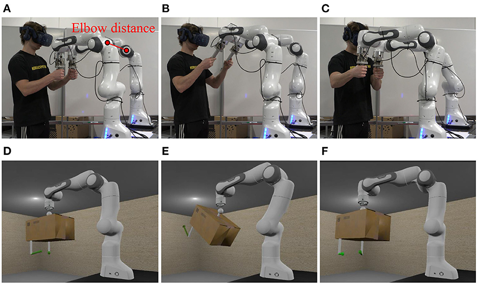
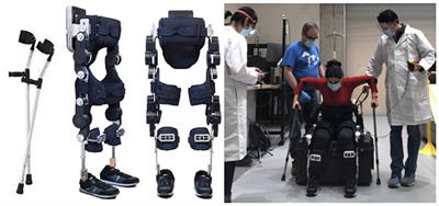
2. Overview of PREDICTOR 2.1. System hardwareAs shown in Figure 1, PREDICTOR consists of a single- or dual-arm cobot system and a VR headset. A human operator uses one or two hand(s) to grip one or two real handle(s) mounted at the end-effector(s) of cobot(s) (depending on the task type). The cobot system is used as an integrated haptic device, which makes the operator feel as if he/she co-manipulated a virtual object with a virtual cobot, which can be seen through a VR headset. Virtual handle(s) corresponding to the real handle(s) is/are attached to the virtual object. It is worth mentioning that the PREDICTOR setup might resemble some teleoperation (Hulin et al., 2011) or telepresence (Buss et al., 2010) systems at first glance, but they function completely differently: while the operator uses two master arms to teleoperate two real remote arms independently in the teleoperation and telepresence, the operator uses the two master arms/real handles as part of a single virtual object co-manipulated by a virtual robot in the physical emulation of PHRC.
Figure 1. Setup of PREDICTOR consisting of a dual-arm robot system (Franka Emika Panda) and a VR headset (HTC VIVE Pro Eye).
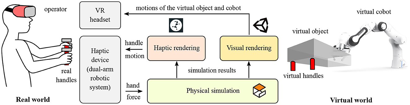
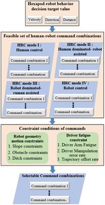
2.2. Software modulesAs shown in Figure 2, The software of PREDICTOR includes three modules: physical simulation, haptic rendering and visual rendering modules. The physical simulation module is responsible for the physical simulation of the dynamic behavior of the coupled human-robot collaborative system, which is implemented in an open-source robotics simulator, Gazebo. It receives the forces/torques applied by the human hands at the two real handles as inputs, which drive the whole simulation of the system along with the virtual cobot controller in question. This module outputs the virtual handle motion as an input (reference) for a haptic rendering module, which uses a motion controller of the dual-arm system to control the real handles to track their virtual counterparts. The physical simulation module also outputs the motions of the virtual object and the virtual cobot, which are visualized by Unity and fed back to the operator through the VR headset, that is, visual rendering module. In this way, the haptic and visual feedback are combined to enhance the realism of the PHRC tasks to be emulated by the PREDICTOR.
Figure 2. Schematic diagram of PREDICTOR and its components. The hardware includes a dual-arm robotic system as a haptic device and a VR headset. The software consists of three modules including physical simulation, haptic rendering and visual rendering modules.
2.3. Features and benefits 2.3.1. Admittance-type haptic deviceAccording to the control scheme of a haptic device, there are two broad classes of haptic devices: admittance-type and impedance-type devices. Admittance-type haptic devices sense the force/torque applied by the operator and constrain the operator's hand position to match the appropriate deflection or motion of a simulated object in a virtual world. In contrast, impedance-type devices sense the position of the operator, then applies a force/torque to the operator according to the computed behavior of the simulated object. In our PREDICTOR, the admittance type was chosen to implement the haptic rendering module for four reasons listed below:
• Admittance-type haptic devices can avoid developing an algorithm of collision detection between an avatar of the tool gripped by the operator and the objects in a virtual environment and an algorithm of force response for calculating the interactive force between them in order to drive the simulation (Salisbury et al., 2004). In our case, the virtual handle (avatar) is already attached to (in contact with) the virtual object. It is more convenient to use the force/torque sensed by a Force/Torque (F/T) sensor mounted between the handle and the end-effector of the real robot to drive the simulation instead of using the collision detection and force response algorithms to transform the motion input to the force input for the simulation.
• Since PREDICTOR is targeted at the safety and ergonomics research in PHRC, the real interactive force in an admittance-type haptic device is more desirable for human behavior study than the artificial interactive force calculated by the collision detection and force response algorithms in an impedance-type haptic device.
• A motion controller in the haptic rendering of an admittance-type device is in favor of the implementation of the kinematic constraint between the two real handles imposed by the rigid body constraint between their virtual counterparts attached to the same object.
• Impedance-type haptic devices require the real robots to be torque-controlled. However, more commercially available robots are position-controlled, e.g., Universal Robots. Selection of the admittance type can widen the uptake and applications of the PREDICTOR.
2.3.2. Risk-controlled and flexible emulatorWhen a human coworker and a cobot co-manipulate one heavy and bulky object (e.g., a car engine), it is risky to validate the safety of the whole process through actual experiments since any accidents in the experiments can seriously hurt the human coworker, for instance, the abnormal behavior of the designed cobot controller can generate a large adverse force on the coworker and cause joint injuries or make the object fall down and hurt his/her legs or feet. Through the PREDICTOR, it is beneficial to analyze the operator reactive behavior in response to the cobot, evaluate the risk of the task in terms of various biomechanical quantities of the human body (e.g., muscle force and joint torque), and conveniently intervene in the process to respond to emergent and dangerous events (e.g., halt the system in time when the monitored interactive force exceeds a safe threshold value) without all the safety concerns in relation to the real experiments. Therefore, PREDICTOR is a risk-controlled test bench to enable the assessment of whether the proposed human-robot collaboration solutions are safe, ergonomic and deployable.
In addition, PREDICTOR is a general and flexible platform for emulating various types of PHRC tasks. To test a different task, what we just need is to deploy a different controller on a virtual cobot and/or use another model for a different co-manipulated object without actually fabricating it out. If the positions of the virtual handles on the co-manipulated object are changed, the dual-arm system can be easily reconfigured to position the real handles consistent with their virtual counterparts. In this sense, the dual-arm system is better than a single arm with a rigid link connecting the two real handles to the arm end-effector since a new link needs to be fabricated every time the virtual handles' positions are changed. Through the PREDICTOR, we can figure out the best setting (e.g., the best handle positions), optimize the task and the controller (and even the mechanical design of the cobot), and train the operator before real PHRC experiments, which are generally costly in terms of the fabrication cost and the preparation of the whole setup.
3. Implementation of software modules 3.1. Physical simulation moduleThe open-source robotics simulator, Gazebo, is used in the physical simulation module to simulate a PHRC system, in which a virtual cobot and a virtual object can be modeled in URDF format and connected in Gazebo in a way depending on the PHRC task to be emulated. One or two virtual handle(s) as the avatar(s) of the real handle(s) is/are attached to the virtual object. The force/torque applied on the real handle(s) by the operator is sent into Gazebo and applied on their virtual counterpart(s) to drive the simulation along with a cobot controller to be examined. Because of the nature of PHRC tasks, an impedance controller (Hogan, 1984) can be chosen for the controller of the virtual cobot.
The dynamic model of a robot manipulator is expressed:
M(q)q¨+C(q,q˙)q˙+g(q)=τ-JTFext, (1)where M(q), C(q,q˙) and g(q) denote the inertia matrix, Coriolis and centrifugal matrix and gravity vector of the manipulator, respectively. τ is the vector of robot joint torques and Fext is the force/torque applied by the robot through its end-effector on the external environment. J indicates the robot Jacobian. The goal of a Cartesian impedance controller is to design an appropriate τ to alter the natural dynamics in Equation (1) to make the robot's end-effector exhibit a virtual mechanical impedance behavior (Khatib, 1987), which can be described by
Λdx~¨+Ddx~˙+Kdx~=Fext, (2)with Λd, Dd, and Kd being the desired mass, damping, and stiffness matrices, respectively. x~ denotes the error of the end-effector position and orientation compared to a desired reference. The feedback of Fext can be avoided when Λd is set to be identical to the robot natural inertia Λ (Ott, 2008). Kd is designed according to the emulated PHRC task while Dd can be further designed based on the designed Kd by using the double diagonalization design approach (Albu-Schaffer et al., 2003). This Cartesian impedance controller is used for the virtual cobot in Gazebo in the validation experiments in Section 4.
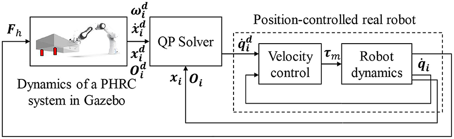
3.2. Haptic rendering moduleAdmittance-type control scheme is used to realize the haptic rendering module. As shown in Figure 3, the forces/torques, Fh, applied by the human operator on the two real handles are measured by F/T sensors, sent into Gazebo and applied on the same positions of the corresponding virtual handles. These forces/torques are monitored in real time and if they exceed predefined safe threshold values, the dual-arm robot system will be halted to guarantee the safety of the operator. The physical simulation of a virtual PHRC system in Gazebo will be driven by the transmitted forces/torques together with a controller of the virtual cobot. The motion states of the two virtual handles, i.e., the position and orientation (xid, Oid,i=1 or 2) and the linear and angular velocities (x˙id, ωid), are measured and used as the targets the real handles try to track as much as possible. Traditionally, differential Inverse Kinematics (IK) techniques can be employed to solve for the corresponding desired joint velocities, q˙id. However, some constraints of real robots like the joint angle/velocity limits and singularities can make the performance of these IKs deteriorate. Quadratic Programming (QP) techniques are becoming more popular and robust to solve the IK problem by transforming the exact tracking problem into an optimization problem (i.e., minimizing the tracking error), especially when the numbers of the robot DoFs and constraints are large (Zhou et al., 2016). A QP solver is therefore used in our case to solve for q˙id, which will be used as the control command for our real dual-arm robot system in velocity control mode. The structure of this control scheme resembles that of a standard admittance control with an inner motion control loop and an outer admittance control loop. The difference is an impedance behavior is rendered at the end-effector of a robot through the outer loop in the admittance control while the dynamic behavior of a PHRC system exhibited at the end-effector(s) is rendered through the outer loop in our control scheme. The stability of the system can be ensured provided that the equivalent bandwidth of the inner control loop is larger than the equivalent bandwidth of the outer control loop (Siciliano et al., 2009).
Figure 3. Implementation of the haptic rendering module based on an admittance-type control scheme.
A QP optimization problem has a general form as follows:
minX 12XTPX+cTX, (3) s.t. AX=b, (4) Xlb≤X≤Xub, (6)where X is the target variable to be optimized, and P, c, A, b, G, h, Xlb and Xub are the parameters to form the problem-specific objective functions and constraints. The construction of these matrices and vectors in our QP optimization problem will be introduced in the following.
3.2.1. Objective functionIn this study, the joint velocities of the two robots are chosen and stacked as the unknown column vector variable, i.e., X=((q˙1d)T,(q˙2d)T)T∈ℝ2n (assume each robot has n controlled joints.). In order to make the real handles to track the motion of their virtual counterparts as much as possible, the objective function is designed as:
minX 12∥JX-vr∥2, (7)where ∥·∥ is Euclidean norm, J is the Jacobian of the dual-arm robot system and vr is the reference velocities of the two real handles calculated by the velocity-based control (Nakanishi et al., 2008):
J=(J1OOJ2)∈ℝ12×2n, vr=(v1rv2r)∈ℝ12, (8) vir=(x˙id+Kp(xid-xi)ωid+Ko(-ηidϵi+ηiϵid-S(ϵid)ϵi))∈ℝ6, (9)where J1 and J2 are the geometric Jacobians of the two robots. xi denotes the position of the real handle i. and are the unit quaternions of the real and virtual handles of robot i, respectively. Kp and Ko are the translational and rotational coefficients. S(·) is a skew-symmetric operator. The objective function in Equation (7) can be equivalently rewritten to the general QP form as in Equation (3) where P = JTJ and c = −JTvr with a constant term 12vrTvr dropped out.
Manipulability optimization can also be included in the objective function to drive the robot system to avoid the singularities for better tracking performance and stability. A translational manipulability Jacobian, Jm∈ℝ2n, which relates the change rate of manipulability of the dual-arm system to its joint velocities X, can be calculated by the robot Hessian tensors introduced in Haviland and Corke (2021). In this case, c=-JTvr-αJm can be used with a scalar weight α for balancing the handle tracking and the manipulability optimization.
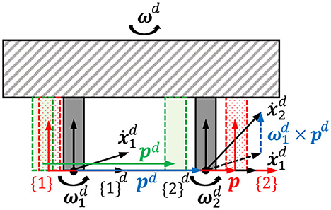
3.2.2. Rigid body constraint between two handlesBy minimizing the objective function, the real handles try to track the motions of the virtual handles as much as possible, which means the tracking errors are allowed to occur in some cases where the tracking performance is sacrificed by optimizing the manipulability more or the robot system is close to its singular configuration. In those cases, the relative position and orientation between the two real handles still remain unchanged as a rigid body constraint imposed by their virtual counterparts attached to the same rigid body. This means that the proprioception of relative position between two hands is prioritized over the exteroception of exact positions of the handles for better realism perceived by users. For instance, the green handles are considered a better tracking compared to the red handles shown in Figure 4 because the distance between green handles are the same as the distance between the gray handles, which represent the virtual handles in the simulator. This rigid body constraint is implemented by the equality constraint (Equation 4) at the velocity level. Assume two reference frames, d and d, are attached to the two virtual handles while and are attached to the two real handles shown in Figure 4. The angular velocities of d and d, ω1d and ω2d, are identical because angular velocity is an attribute of the rigid body and independent of the position of reference frame. The linear velocities of the origins of the two frames, x˙1d and x˙2d, holds a relationship x˙2d=x˙1d+ω1d×pd where symbol × denotes cross product and pd is a displacement vector from handle 1 to handle 2. So, the equality constraint between the velocities of and can be formulated as:
AX=b, A=(J1l+S(p)TJ1a,-J2lJ1a,-J2a)∈ℝ6×2n, b=(-Kp′(pd-p)-Ko′(-η1ϵ2+η2ϵ1-S(ϵ1)ϵ2))∈ℝ6, (10)where Jil∈ℝ3×n and Jia∈ℝ3×n are the upper and lower submatrices of Ji which influence the linear and angular velocities of handle i, respectively, that is, Ji=(JilT JiaT)T. The equality constraint in Equation (10) tries to eliminate the relative translational and rotational tracking errors (b) between the two real handles to make them obey the rigid body motion law as much as possible. For example, the red handles in Figure 4 can be constrained to move to the green ones even though the absolute handle tracking is not perfect, which is handled by the objective function (Equation 7).
Figure 4. Rigid body constraint between the two real handles imposed by their virtual counterparts, which are attached to the same rigid body in the simulator.
3.2.3. Collision avoidance constraintThe method named velocity damper (Faverjon and Tournassoud, 1987) is introduced for collision avoidance between two robot arms. Since the two bases and the two end-effectors are constrained apart from each other, respectively, only elbow collision avoidance is focused here. Elbow distance, d, is defined as the distance between the origins of two link frames located at the two elbow centers shown in Figure 5A. If the two elbows move closer to each other, the change rate of d is constrained as
d˙≥-ξd-dsdi-ds, for d<di, (11)where ξ is the positive damping coefficient. Security distance, ds, is the minimum distance that d could be. This inequality implies that, when d is smaller than an influence distance, di, the two elbows will try to decrease their approaching speed and prevent themselves being too close since d could never be smaller than ds.
Figure 5. Snapshots of an experiment of scenario 1 at 5s (A), 18s (B) and 28s (C), and the corresponding snapshots of the VR scene in the visual rendering module at 5s (D), 18s (E), and 28s (F).
Computing ḋ using the current configuration and the joint velocities of the dual-arm system, the velocity damper inequality becomes
nT(Je1,-Je2)X≥-ξd-dsdi-ds, for d<di, (12)where n ∈ ℝ3 is the unit directional vector from the center of elbow 2 to that of elbow 1. Jei∈ℝ3×n is the translational elbow Jacobian of robot i. Therefore, G=-nT(Je1,-Je2) and h=ξd-dsdi-
留言 (0)