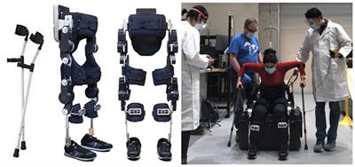
The twenty-first century is the century of the ocean. With the gradual deepening of the development of marine resources in various countries, an increasing number of maritime accidents have led to the loss of a large number of high-value property in the sea. The traditional automatic salvage equipment is designed for the separation of salvage fixtures and underwater search vehicles, and the salvage steps have a low success rate. The underwater salvage robot studied in this article is a claw-type underwater salvage robot, which mainly grabs underwater cylindrical salvage objects, such as training torpedo bomb with failure of a floating system, ship wreck column structure, and so on. In practical engineering application, the mother ship carries the robot sailing to the target water area, the diving depth of the robot is controlled by the armored steel cable after the lifting system is lowered to the target depth, and the underwater search is carried out by following the mother ship through its own power. The robot accurately locates the position of the salvage. Finally, the attitude adjustment thruster is turned on to adjust the relative position and use the lower claw of the robot to grab the salvage object, which is then recovered by the mother ship as shown in Figure 1. Underwater salvage robots working in complex and harsh sea conditions for a long time will face the following challenges in control design: 1) When the control process is affected by modeling technology, environmental uncertainty and parameter uncertainty, how to realize the high accuracy and high sensitivity control of underwater vehicle under complex sea conditions; 2) The fault-tolerant control effect of the thruster of the underwater vehicle under the condition of unknown faults such as line damage, foreign body damage, and so on; 3) In the case of lack of power in the fault state, the high-frequency control system and high-load transfer propulsion system leading to accelerated wear damage of the fault thruster; and 4) the isolation adaptation of multiplicative coupling faults and the accurate compensation of the controller.
For actuator fault-tolerant control, there are passive fault-tolerant control (Jin, 2016) and active fault-tolerant control (Zhao et al., 2018). The design principle of passive fault-tolerant control is to enhance the robust performance of the controller and improve the control effect of equipment in the presence of external disturbances and internal faults, but the strong robustness of passive fault-tolerant control is worse than that of active fault-tolerant control. At present, the mainstream solution to equipment actuator failure is active fault-tolerant control, in which many scholars only study one of the cases: either invalid fault or stuck fault. Thruster invalid failure is due to oil leakage in the hydraulic system or sea water corrosion and other force majeure factors caused by part of the propeller blade damage, resulting in much less the actual output power than the expected power. This kind of fault is common in practical engineering, but it is difficult to control the deep coupling between the fault and the system model. Most of them improve system robustness by magnifying parameter excitation persistence or the excitation threshold (Chen et al., 2018) and design robust fault observers to increase the accuracy of system compensation and improve system robustness (Park and Yoo, 2016). The reason for the stuck fault is that the propulsion system cannot effectively control the pitch of the propeller caused by the suction of foreign bodies such as underwater suspended plants or the control system loses control of the thruster due to the failure signal of the transmission line controlled by the fuselage. The propulsion system maintains the final thrust output of effective control, which will make some of the thrusters completely out of control and cause strong interference to the system as a whole. In order to solve the problem of stuck faults caused by communication faults, the residual system constructed by the model is approximated to enhance the robustness of the system to faults and external disturbances (Yan and Ren, 2021). In order to improve the control effect of the system fault, Zong et al. (2020) extended the system fault to the system state quantity and designed an observer to approximate the system fault state and external disturbance state. Van et al. (2016) have designed an active fault-tolerant control algorithm for the non-singular terminal sliding surface to solve the external unknown disturbance and system jam fault. The previously mentioned five control algorithms mainly solve the thruster failure or paranoid jamming in the system, but the fault situation in the actual engineering control is often unpredictable, which makes the application environment considered by the algorithm design is not comprehensive.
To improve the ability of the controller to deal with multiple faults, the solution presents two schools: 1) establish a more complete fault model and 2) add a fault detection module to assist control decision-making. A more perfect dynamic model of fault description is established, and then adaptive robust control such as adaptive sliding mode controller (Hao et al., 2020) is designed to estimate fault information and unknown disturbance upper bound of the system (Zhu et al., 2021). The engineering problem of complex fault of actuator in bad sea condition is solved, but the control phenomenon of deep coupling between actuator fault and dynamic uncertainty of system model occurs. The design idea of this school is to design fault-tolerant controller directly for coupling parameters. However, there will be the problem that fault-tolerant control compensation is not sensitive and is easily affected by model dynamics. In order to solve the problem of fault tolerance in the process of ship motion, Benetazzo et al. (2015) used the parity space method and Luenberger observer to detect the fault of the system. In order to further improve the control accuracy, Kalman filter (Cristofaro and Johansen, 2014) interference compensation is designed on the basis of the controller for fault-tolerant control of the overactuated marine vessel. When there is a fault of the actuator, a new dynamic state inevitably appears. It is a processing idea to reconstruct the power (Yang et al., 1999; Liu et al., 2022) of the actuator after fault detection and carry out fault-tolerant control. The earlier design scheme needs to rely on the feedback of the system fault detection module to the system control, but in the actual project, the complex fault situation, environmental noise, and the particularity of the system structure will lead to misreport and underreport. It will directly affect the accuracy and sensitivity of the fault-tolerant controller.
The earlier control schemes only consider the fault-tolerant control for actuator faults and seldom consider that the load capacity of the propulsion device of the system decreases after the actuator failure, and the high-frequency regulation load will lead to further damage to the propulsion device. This makes the equipment out of control without the knowledge of the operator. Now the event trigger mechanism has a great advantage in reducing the signal transmission frequency and reducing the thruster adjustment times. Among them, the trigger environment of the preset event (Tabuada, 2007; Xu et al., 2018; Wang et al., 2019) is more common, which makes the system feedback enter the preset event trigger evaluation condition and input the actuator, and the trigger effect is also highly dependent on the preset event trigger condition. Therefore, the design of dynamic event trigger mechanism which adjusts with time and system state has become the key factor to effectively reduce the load of system regulation. Event triggering mechanism has been effectively applied to trajectory tracking (Deng et al., 2019b; Chen et al., 2022), path tracking (Li et al., 2020), and formation control of surface and underwater vehicles.
In order to solve the earlier problems, this article first designs and improves a more universal fault model of the underwater salvage robot, and designs a proportional logarithmic projection analytical overdrive trigger controller according to the assembly features of the robot propulsion system to control the dynamics of the outer loop. The separation characteristic of the projection analytical controller is used to isolate and adapt the deeply coupled fault feature state. By making the control system of the underwater salvage robot get rid of the assistance of the fault detection system and the monitoring and sensing system of the thruster as shown in Figure 2, it can still achieve accurate fault compensation and reasonable distribution of power to reduce the output of the fault thruster. The terminal sliding mode observer is used to observe and compensate the bounded disturbance of the external ocean current and the paranoid fault disturbance of the thruster in real-time, and the adaptive extension network is used to fit the dynamic uncertainty of the system online to improve the accuracy and sensitivity of the system. In order to solve the problem of frequent adjustment and high output after system thruster failure, the dynamic event trigger mechanism is introduced. Finally, it is proved that the controller is bounded and convergent in trajectory tracking control by Lyapunov stability analysis (Deng et al., 2019a).
According to the motion characteristics of the underwater salvage robot, the motion of the surge, sway, and yaw of the underwater robot is considered to be decoupled, and the water surface control ship controls the active water depth of the underwater robot by releasing the cable length, so the underwater robot heave, roll, and pitch motion dimensions are ignored. The motion model of the underwater salvage robot (Corradini et al., 2010) is simplified to a three-degree-of-freedom underwater motion model in the horizontal longitudinal-transverse plane according to the working environment and design features. The surge, sway, and yaw of the underwater salvage robot are controllable variables of the control system. In the reference article Fossen (2011), the position vectors of the underwater vehicle coordinate system and the geodetic coordinate system are [x, y, ψ]T. Under geodetic coordinates, the position coordinates of the underwater vehicle are (x, y). The velocity vector is [u, v, r]T. Therefore, the motion model of this underwater salvage robot is described as follows:
, η=pq,p,q are positive odd numbers and satisfy 1 D^˙(t)=1ηE-1Δ˙2-η+εS+(γ+Ĥ)sign(S) (23)
Ĥ˙v=ηζ∑i3EiFi|Si| (24)
In the equation, H is an upper bound on Ḋ(t), D^(t) and Ĥ are estimates of D(t) and H, respectively, E = diag. b1, b2, and b3 greater than zero, F=diag[Δ˙uη-1,Δ˙vη-1,Δ˙rη-1]. ε, γ, and ζ are normal numbers. By using Lemma 1, taking the derivative of Equation (20), we can get:
Δ˙=Ẏ-Ŷ˙ (25)
Substituting (Equations 19, 21) into Equation (25), we can obtain:
Δ˙=Ẏ-Ŷ˙=D(t)-D^(t) (26)
Δ¨=Ḋ(t)-D^˙(t) (27)
Taking the derivative of S leads to:
Ṡ=Δ˙+ηEFΔ¨ =Δ˙+ηEF(Ḋ(t)-D^˙(t) (28)
Substituting (Equation 23) into Equation (28), we can get:
Ṡ=ηEF[Ḋ(t)-εS-(γ+Ĥ)sign(S)] (29)
The stability of the observer is analyzed, and the Lyapunov function is set as,
Vd=12STS+12ζH~2 (30)
Taking the derivative of Vμv leads to:
V˙d=STS˙−1ζH˜H^˙ =−εηSTEFS−γη∑i=13EiFi|Si|−1ζH˜H^˙+η∑i=13EiFi(SiD˙(t)−|Si|H^) ≤−εηSTEFS−γη∑i=13EiFi|Si|−1ζH˜H^˙+η∑i=13EiFi(|Si|D˙(t)−|Si|H^) =−εηSTEFS−γη∑i=13EiFi|Si|−1ζH˜H^˙+η∑i=13EiFi|Si|H˜ (31)
Substituting (Equation 24) into Equation (31), we can get:
V˙d≤-εηSTEFS-γη∑i=13EiFi|Si| (32)
The observer is stable because of V˙d<0, and the system state converges to the sliding mode surface in finite time S = 0 (Feng et al., 2002), so the system can fully estimate D(t) in finite time, D(t)=D^(t).
4.3. Design of projection analytical overdrive controller for underwater fishing robot
Assumption 1: The weight W* of the Radial Basis Function (RBF) neural network used to approximate the unknown vector is bounded. There are positive constants WM, and ‖W*‖≤WM, ε is the neural network approximation error.
Assumption 2: The external environmental interference, system velocity, and acceleration are bounded and smooth in the range of t ∈ R+, Interference force / torque τwu, τwv, τwr acting on the robot itself. Suppose there are several unknown constants, τwumax > 0, τwvmax > 0, τwrmax > 0, consistent with |τwu| < τwumax, |τwv| < τwvmax, and |τwr| < τwrmax.
System velocity error (Equation 33),
Ẏe=Ẏd-Ẏ=Ẏd-M-1Gςθmax1ln (θmax+1)sig(θ(t))ln (|θ(t)|+1) -M-1Gχθs(t)-M-1d(t)+F(x) (33)
In the equation, Ye=[ue,ve,re]T,ue=ud-u,ve=vd-v,re=rd-r. The RBF neural network algorithm is designed to approximate the system dynamic uncertainty,
F(x)=W*Tψ(z)+ε (34)
Ẏe=Ẏd-Ẏ=Ẏd-M-1Gςθmax1ln (θmax+1)sig(θ(t))ln (|θ(t)|+1) -M-1Gχθs(t)-M-1d(t)+W*Tψ(z)+ε (35)
Lyapunov function is designed for system velocity error
Vv=12YeTYe+∑i=1mς~i2(t)2yi+∑i=1nΘ~i2(t)2 (36)
In the equation, m = 4, n = 3, taking the derivative of Lyapunov (Equation 36), we obtain:
V˙v=YeTẎe+∑i=1mς~i(t)ς^˙i(t)yi+∑i=1nΘ~i(t)Θ^˙i(t) (37)
V˙v=Ye T[Y˙d−M−1Gςθmax1ln(θmax+1)sig(θ(t))ln(|θ(t)|+1


留言 (0)