
記住我
Bicortical 3.5 mm fully threaded lag screw fixation of medial malleolus fractures provides improved pullout strength,1 and over 3 times the maximum torque generated2 compared with partially threaded unicortical 4.0 mm screws.
To achieve even spacing for placement of two 3.5 mm cortical screws through the medial malleolus, the maximum diameter of the fractured surface needs to be 5×3.5=17.5 mm so that there is at least 1 screw diameter distance between anterior cortex and anterior screw, posterior cortex, and posterior screw and between the 2 screws. Often times, the size of the medial malleolus fracture is smaller than 17.5 mm in width, and this may not always be feasible. Moreover, even in cases where the medial malleolus fracture is larger than 17.5 mm, the placement of two 3.5 mm screws narrows significantly the room for any imperfections in the spacing of the screws.
We describe a technique for insertion of two 2.7 mm bicortical screws in a lag fashion for medial malleolus fractures that is simple and cost-effective. To our knowledge, the use of 2.7 mm screws for medial malleolus fracture has not been described before.
SURGICAL TECHNIQUEThe medial malleolus fracture is approached and reduced usually with a pointed reduction forceps or according to the surgeon’s preference. Then a 2.0 mm trocar tip Kirschner wire (150 mm long) from a small or mini fragment set is placed at medial malleolus. This 2.0 mm wire serves as the drill for the 2.7 mm screw; it also provides additional provisional fixation of the fracture. The starting point and the direction of the wire is checked with biplanar fluoroscopy. The direction should be perpendicular to the fracture plane. The 2.0 mm wire is advanced until the lateral or posterior cortex of tibia is encountered. As this is a solid wire, it does not deflect the way the drill bit would.3 At this point, the wire is not advanced through the cortex.
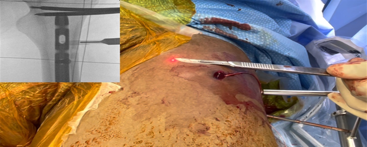
Then we use a longer trocar tip 2.0 mm Kirschner wire (usually 230 mm long) from a Steinman pin set. The reason we choose the second wire to be longer than the first one is to have greater clearance and avoid any interference between the wire driver and the first wire. This helps so the second wire can be driven parallel to the first one. The wire tip is placed anteriorly or posteriorly to the first wire. The starting point is checked with biplanar fluoroscopy. The direction is visually referenced off the first 2.0 mm wire without fluoroscopy. We do not use the 2.0 mm triple guide to get the second wire parallel to the first one as has been described,4 because we have noticed that deflection (convergence or divergence) can easily occur, and the predetermined spacing may not be desirable. The long 2.0 mm wire is then advanced again until the lateral or posterior cortex of the tibia is encountered without penetrating the cortex (Fig. 1A). The reason the wire is not penetrating the cortex is to facilitate screw length measurement through the subtraction technique without using fluoroscopy.
 FIGURE 1:
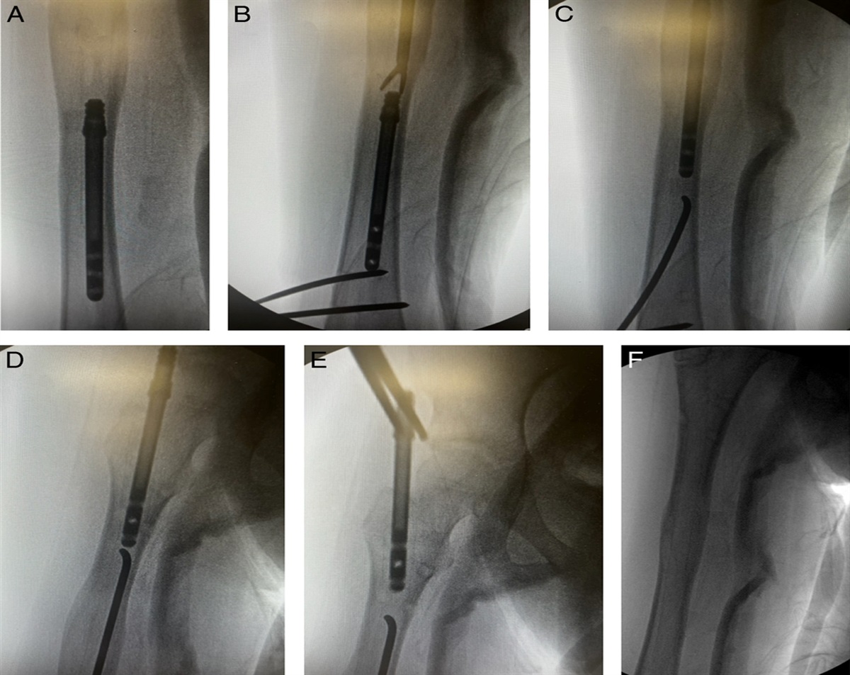
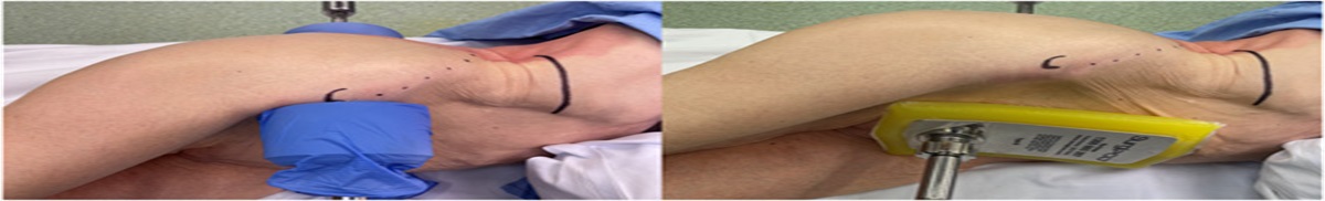
 A, A short and a long 2.0 mm wires are inserted across the medial malleolus fracture. A 2.0 and a 2.7 mm drill sleeve is passed over the 2.0 mm wire. B, The long 2.0 mm wire and drill sleeve have been removed and a 2.7 mm drill (cannulated in this case) is placed over the 2.7 sleeve. C, The first 2.7 mm screw is inserted. Appropriate direction is maintained by visual referencing the short 2.0 mm wire. D, A line is drawn on the skin parallel to the direction of the wire to help guide the second screw in the right direction. E, The second screw is inserted. F, Anteroposterior and lateral fluoroscopic intraoperative images of left ankle medial malleolus fracture fixed with 2 bicortical 2.7 mm screws.
The same length wire is then placed on the bone next to the first or second wire, and using a ruler we measure the length of the screws. Since the wire has not pierced the opposite cortex and the fracture is not fully compressed, we add 2 to 6 mm to the measurement [eg, if the length is 59 to 63 mm, we use a 65 mm screw (at that range, screws are available at 5 mm increments)]. After measurement, both 2.0 mm wires are advanced to penetrate the opposite cortex to achieve bicortical purchase for the screws. Depending on the surgeon’s preference, the screw length can be measured with a depth gauge instead of using the subtraction technique.
In the next step, the wires will be exchanged with screws. We prefer to remove first the longer wire as this way, there is less interference between the screwdriver and the other wire. The reduction at this point is helped by the shorter wire and a pointed reduction forceps. For insertion of the screws in a lag technique, the 2.7 mm drill guide is passed over the longer 2.0 mm wire, the wire is removed, and a 2.7 mm cannulated drill bit is used over an appropriate guidewire to overdrill the near fragment (Fig. 1B). The first 2.7 mm screw is then inserted using as a visual reference the other wire (Fig. 1C). As the screw is lag-by-technique, it does not torque the near fragment; therefore, rotation of the fragment does not occur. The same process is then repeated for the second screw. A line is drawn on the skin parallel to the direction of the wire before removal of it (Fig. 1D) as this helps to maintain the direction during screw insertion (Fig. 1E). Final screw tightening is then performed. Fluoroscopy is used to verify the appropriate positioning of the hardware (Fig. 1F). Figure 2 depicts the instruments used in the technique.
 FIGURE 2:
 The instruments needed are a 2.0 and a 2.7 mm drill sleeve, 2 short and 2 long 2.0 mm wires, a ruler (alternatively a depth gauge can be used, not shown here), and a 2.7 mm drill. In the figure a cannulated 2.7 mm drill with its guidewire is shown (Smith and Nephew, Memphis, TN). Similar instruments are available by most fracture implant companies.
The wound is then irrigated and closed in layers. The ankle is immobilized in a splint for 2 weeks, and range of motion exercises is started thereafter. Patients start weight-bearing as tolerated at 4 weeks postoperatively if there is no syndesmotic injury. Figures 3–5 demonstrate the injury, the immediate postoperative, and the 6 months postoperative radiographs of a patient with a displaced medial malleolus fracture fixed with the described technique.
 FIGURE 3:
 Anteroposterior and lateral radiographic images of left ankle revealing a displaced medial malleolus fracture.
 FIGURE 4:
 Anteroposterior, mortise, and lateral radiographic immediate postoperative images of left ankle.
 FIGURE 5:
 Anteroposterior, mortise, and lateral radiographic images of left ankle at 6 months postoperatively.
EXPECTED OUTCOMESLiterature supports the use of bicortical fully threaded lag screws for fixation of medial malleolus fractures with better radiographic and clinical outcomes reported comparing to the use of partially threaded unicortical screws.2 The superior bony compression achieved by bicortical fixation decreases the risk of screw loosening and nonunion, and the stiffer construct allows for early weight-bearing as soon as soft tissues heal, usually at 2 weeks if there is no syndesmotic injury.2 The use of bicortical fixation of medial malleolus fractures is also supported by biomechanical and cadaveric studies showing that it provides additional fixation strength.1,2,5
In the past, a similar technique has been described utilizing 3.5 mm screws for bicortical fixation of medial malleolus fractures.3 In that description, the authors mentioned that smaller diameter screws can be used. In the present study, we give a detailed description of that technique utilizing mini fragment 2.7 mm screws.
With this technique, the wires that hold the reduction also serve as the drill bit for the screws. This way, interference between the provisional fixation wires and the desired screw path is prevented. Moreover, the placement of multiple holes that can lead to fragmentation and loss of reduction is avoided. The technique allows for the placement of 2 screws even in small medial malleolar fragments and is more forgiving, allowing for slight imperfections in the spacing of the screws comparing to 3.5 mm screws. The use of different lengths of 2.0 mm Kirschner wires allows for easier and more precise navigation of the second wire parallel to the first one. Another advantage of using 2.7 mm cortical screws instead of 4.0 mm cannulated screws is that it is much easier to achieve parallelity using 2.0 mm wires than using the thinner guidewires used for the 4.0 mm cannulated screws. This helps to decrease the use of intraoperative fluoroscopy. In addition, sturdier 2.0 mm wires provide more stable provisional fracture fixation during screw placement. The 2.7 mm lag-by-technique screw does not displace the medial malleolus fragment during insertion. In contrast, the torque generated with 4.0 mm partially threaded screw insertion through hard cortical bone can displace the fracture. The 2.7 mm screw head is small, and this helps to decrease hardware prominence. Bicortical fixation provides superior compression of the fracture. The cost of cortical screws is significantly lower to that of cannulated screws.
COMPLICATIONSDisadvantages of the technique include that not all implant companies offer long 2.7 mm screws, and the smaller screw head can make implant removal more difficult. The smaller head of the 2.7 mm lag screw can make overinsertion possible with resultant loss of compression. To prevent this, washers can be used, especially in osteoporotic bone. However, when washers are used, the distance between the screws will increase to accommodate for the washers which may not be feasible for the smaller medial malleolus fractures. Possible difficulties that arise from the use of noncannulated screws are offset from the appropriate use of 2.0 mm wires, drill sleeves, and visual clues to achieve parallel insertion of the screws. From our teaching hospital experience, the learning curve for this technique is short and smooth. No specific complications are associated with this technique, other than the general complications associated with open reduction and internal fixation of medial malleolus fracture.
In conclusion, we describe a technique for bicortical fixation of medial malleolus fractures with two 2.7 mm screws in a lag fashion. It does not require special instrumentation and provides reliable fixation even in small medial malleolus fractures. The technique described could prove a useful adjunct in the trauma surgeon’s armamentarium.
REFERENCES 1. Pollard JD, Deyhim A, Rigby RB, et al. Comparison of pullout strength between 3.5-mm fully threaded bi-cortical screws and 4.0-mm partially threaded, cancellous screws in the fixation of medial malleolar fractures. J Foot Ankle Surg. 2010;49:248–252. 2. Ricci WM, Tornetta P, Borrelli J Jr. Lag screw fixation of medial malleolar fractures: a biomechanical, radiographic, and clinical comparison of unicortical partially threaded lag screws and bicortical fully threaded lag screws. J Orthop Trauma. 2012;26:602–606. 3. Parada SA, Krieg JC, Benirschke SK, et al. Bicortical fixation of medial malleolar fractures. Am J Orthop (Belle Mead NJ). 2013;42:90–92. 4. Meagan MM, Schuberth JM. Fixation of the medial malleolar fracture: a simplified technique. J Foot Ankle Surg. 2008;47:368–371. 5. Meeks BD, Kiskaddon EM, Boin MA, et al. The role of far cortical endosteal fixation for the treatment of medial malleolus fractures: a biomechanical study. J Foot Ankle Surg. 2020;59:2–4.
留言 (0)