
記住我


With the continuous development of robot technology, the application scope of mobile robots is constantly expanding, and the diversification of application scenarios leads to the increase of robots facing complex terrain environments (Zhang et al., 2014; Gao et al., 2020). Wheeled robots have the advantages of high efficiency and high energy utilization on flat roads (Wu, 2020; Xin et al., 2020), but they have poor adaptability to complex terrain. When the height of obstacles is greater than the radius of the wheels, they cannot effectively cross obstacles (Ding and Zhang, 2022). Legged robots have excellent adaptability when moving on the uneven and rough roads, but slow moving speed and low movement energy efficiency have always been technical problems that are difficult to break through (Xin et al., 2019; Xin and Vijayakumar, 2020). To solve this problem, the researchers turned their attention to wheel-legged robots. Wheel-legged robots combine the advantages of wheeled robots and legged robots. Double wheels can maximize energy utilization efficiency and maneuverability, and the leg structure makes the robot more adaptable to complex terrain environments.
At present, scholars have carried out a lot of research on the stability and high obstacle crossing ability of wheel-legged robots in unstructured terrain and have achieved a series of results: Liu et al. (2019, 2022) and Zhang et al. (2019) proposed a bipedal wheeled robot SR600 for logistics in scenarios such as distribution and home services, it can change height while maintaining dynamic balance. The size design of the human body can make it better interact with people. Kim et al. (2014) developed the Wheel Transformer, a variable-diameter wheel-legged robot. When encountering an obstacle, the wheels are transformed into two three-legged wheels to complete the action of crossing over the obstacle. It can overcome obstacles that 3.25 times higher than the wheel radius, but there is also the problem of low efficiency of crossing obstacles. In nature, animals jump over obstacles and avoid enemies attack by jumping (Fei et al., 2012; Cheng, 2021). Inspired by this, the bionic jumping theory was applied to the wheel-legged robot, and the jumping obstacle was realized by the wheel-legged robot (Zhuang et al., 2021; Hao et al., 2022). Chen et al. (2021) studied the jumping of a bipedal wheel-legged robot, proposed a W-SLIP model to characterize the jumping process dynamics, and verified the robot’s jumping performance through V-REP simulation. Bipedal wheel-legged robot Ascento produced by ETH Zurich that adopted a compact design structure and can jump over obstacles while keeping the robot flexible and compact (Klemm et al., 2019; Klemm et al., 2020). The quadruped wheel-legged robot ANYmal (Bjelonic et al., 2019) of ETH Zurich also reflected the advantages of the combination of legged robots and wheeled robots to a large extent. The typical wheel-legged robot Handle developed by Boston Dynamics Ltd (2017). Achieved self-balancing through a dynamic control center, and used a hydraulic drive to jump to a height of 1.2 m (Zhang et al., 2018). At present, wheel-legged robots are still mainly used in simple application scenarios such as logistics handling, while wheel-legged robots suitable for complex terrain environments have been rarely reported.
Aiming at the problems that the wheel-legged robot is not stable in the complex terrain environment, a jumping wheel-legged robot is proposed in this paper, and an adaptive retractable wheel-leg mechanism is designed to keep the body parallel to the ground to achieve smooth obstacle-surmounting. The main motion forms of the robot include wheel and wheel-leg movement modes, and the modes are switched by the rotation of the hip motor. The wheel movement mode is used on flat terrain, and the wheel-leg movement mode is used on obstacles and rough terrain to improve energy utilization efficiency. In the wheel-leg movement mode, the robot cannot only use the wheels to move quickly and stably, but also jump over obstacles through the expansion and contraction of the wheel-leg linkage mechanism. The paper is structured as follows: In Section “Kinematics and dynamics analysis,” the robot is introduced and the kinematics and dynamics modeling, including the self-balancing dynamics model and the jumping dynamics model. In Section “Analysis of obstacle crossing conditions,” the wheeled overcoming obstacles and jumping over obstacles are analyzed respectively, and the conditions for overcoming the obstacles are obtained. The control system is presented in Section “Robot Control System,” divided into self-balancing and jump control. Section “Simulation and experiment” conducts simulation tests on robot crossing obstacles in different terrains, and conducts actual test verifications. The paper is concluded in the last section.
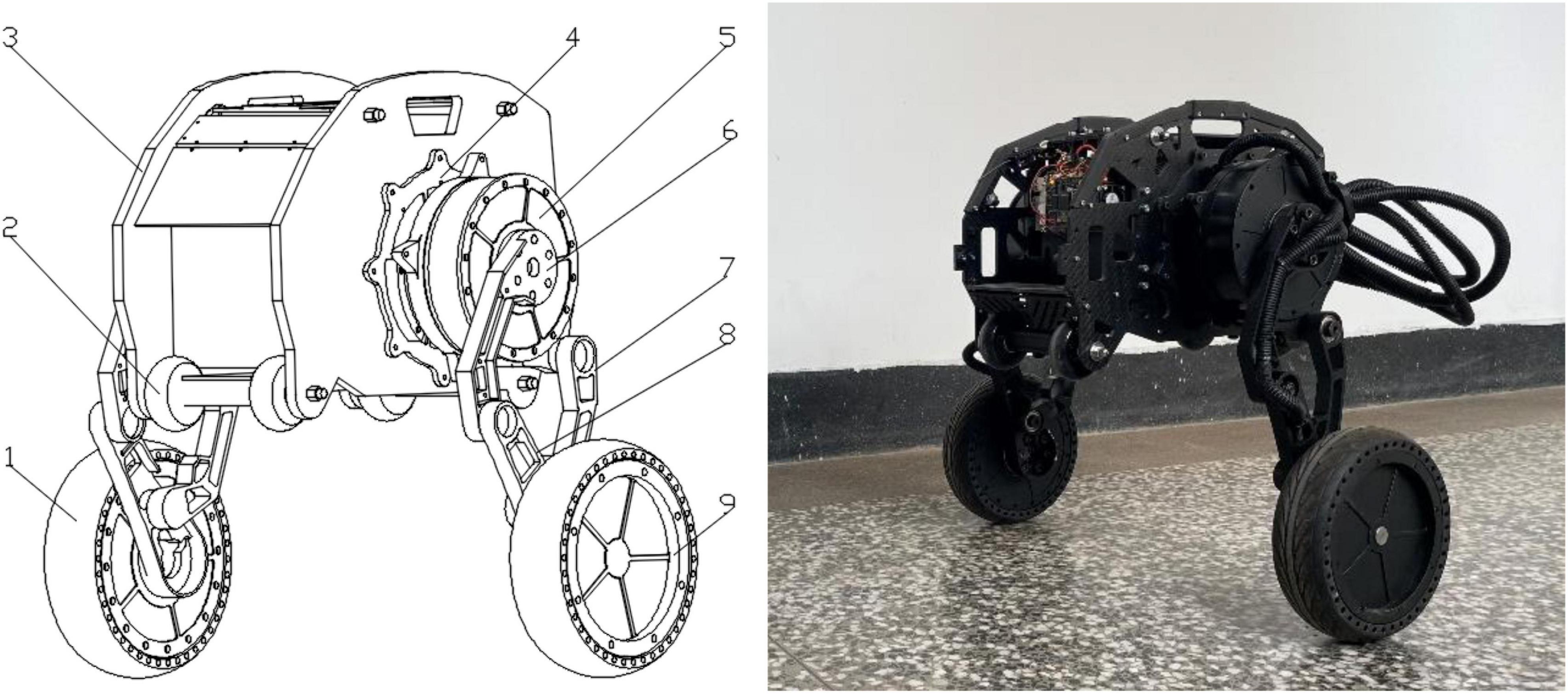
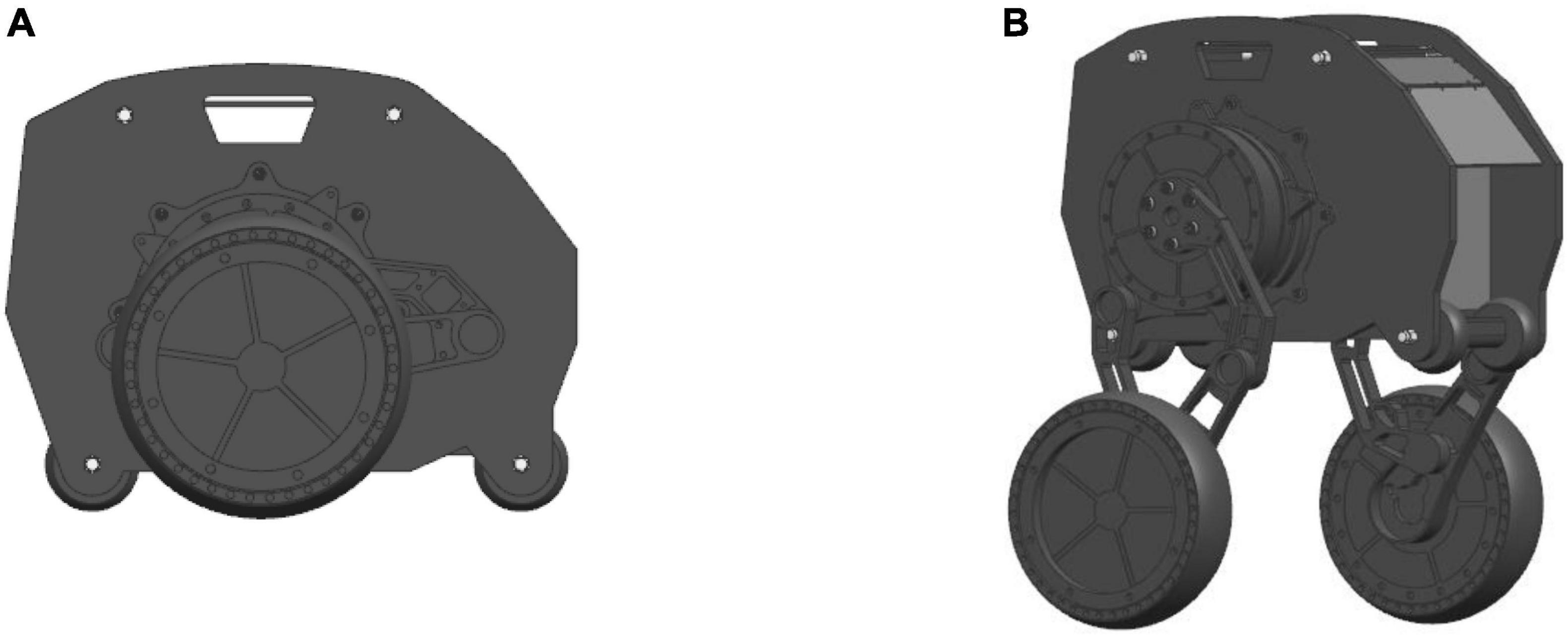
Kinematics and dynamics analysisThe overall structure design of the robot is shown in Figure 1, which consists of the body, six motors, two linkage mechanisms, two pairs of universal wheels and two wheels. The two waist motors (including No. 4 in Figure 1) are hidden inside the body, and two motors are installed in the left and right wheels to drive the wheels to move. The waist motors are used to adjust the pitch angle of the body, and the hip motors are used to control the robot to change the height of the body and realize the jumping function. The hip motor rotates, and under the action of gravity, the connection between the Connecting rod 2 and the hip motor rotates around the rotation axis of the hip joint to realize the expansion and contraction of the leg linkage mechanism. The height of the body is raised and lowered through the expansion and contraction of the linkage mechanisms, and the wheel-leg linkage mechanisms contract and stretch in a short time, completing the accumulation and release of the energy required for jumping, and the robot realizes the jumping action. The wheel movement mode and the wheel-leg movement mode are shown in Figures 2A,B below, respectively.
Figure 1. Schematic diagram of the robot structure. 1. Right wheel (driving wheel); 2. Universal wheel; 3. Body; 4. Waist motor; 5. Hip motor; 6. Connecting rod 1; 7. Connecting rod 2; 8. Connecting rod 3; 9. Left wheel (driving wheel).
Figure 2. Schematic diagram of robot motion posture: (A) Wheel movement mode; (B) Wheel-leg movement mode.
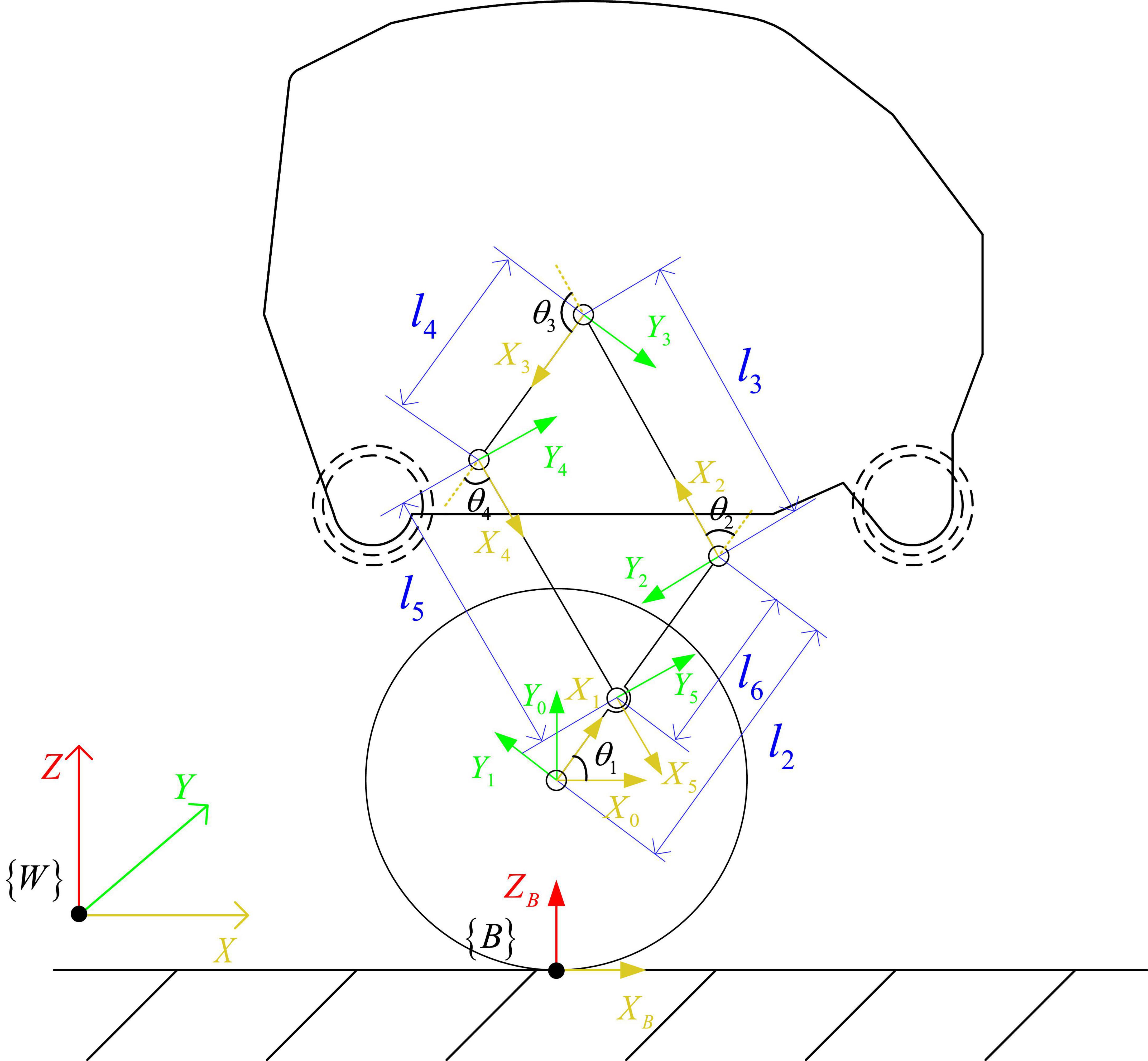
Kinematic modelingAs shown in Figure 3, the kinematic model of the standing posture of the wheel-legged robot is established. is the world coordinate system, the Z axis is vertically upward, the X axis is perpendicular to the Z axis and points to the right end, and the Y axis direction is determined according to the right-hand rule. In order to simplify the kinematics problem, the base coordinate system is established at the contact point between the wheel and the ground, the direction is parallel to the world coordinate system, and the coordinate system is established at the center of the wheel. The coordinate system is established at the connection between the Connecting rod 3 and the wheel, the coordinate system is established at the connection between the Connecting rod 1 and the Connecting rod 3, and the coordinate system is established at the position shown in the Figure 3 in turn. The Zi(i = 1∼5) axis of the link is along the joint. The positive direction of the axis is placed perpendicular to the surface of the paper, the positive direction of the Xi axis points to the common perpendicular of the i axis and the i+1 axis, and the direction of the Yi axis is determined by the right-hand rule.
Figure 3. Kinematics model of robot.
In the kinematic model of Figure 3, ai–1 is the length of the connecting rod, αi−1 is the rotation angle of the connecting rod, di is the offset distance of the connecting rod, θi is the joint angle, li is the distance between the origin of the coordinate system and the origin of the coordinate system in the Z-X plane. where i = 1∼5 is the rotational joint of the robot, d1 = 0.026m, d2 = 0.021m, d3 = 0.016m, d5 = 0.016m. l2 = 0.14m, l3 = 0.14m, l4 = 0.09m, l5 = 0.14m, l6 = 0.09m, the robot wheel radius r = 0.095m.
According to the established kinematics model, the forward kinematics is solved, and the connecting rod transformation matrix is obtained as:
T10=[C1-S100S1C10000100001] ,T20=[C12-S120C1l2S12C120S1l2001-d1-d20001](1)
T30=[C123-S1230C1l2+C12l3S123C1230S1l2+S12l3001-d1-d2-d30001] ,T40=[C1234-S12340C1l2+C12l3+C123l4S1234C12340S1l2+S12l3+S123l4001-d1-d2-d30001](2)
T50=[C1234-S12340C1l2+C12l3+C123l4+C1234l5S1234C12340S1l2+S12l3+S123l4+S1234l5001d5-d1-d2-d30001](3)
Where, C1234 is the meaning of cos(θ1 + θ2 + θ3 + θ4), S1234 is the meaning of sin(θ1+θ2+θ3+θ)4.
The robot is a parallelogram linkage mechanism, and the robot body is expected to be parallel to the ground while maintaining balance, so the constraint equation is attached:
θ2=θ4=π-θ3,θ1=12θ3(4)
Use UG software to analyze the position of the center of mass of each rod and the body of the robot, and obtain the coordinates of the center of mass c1 of the Connecting rod 3, the center of mass c2 of the Connecting rod 1, the center of mass c3 of the body, and the center of mass c4 of the Connecting rod 2 relative to the X-Y plane of the , , , coordinate system:
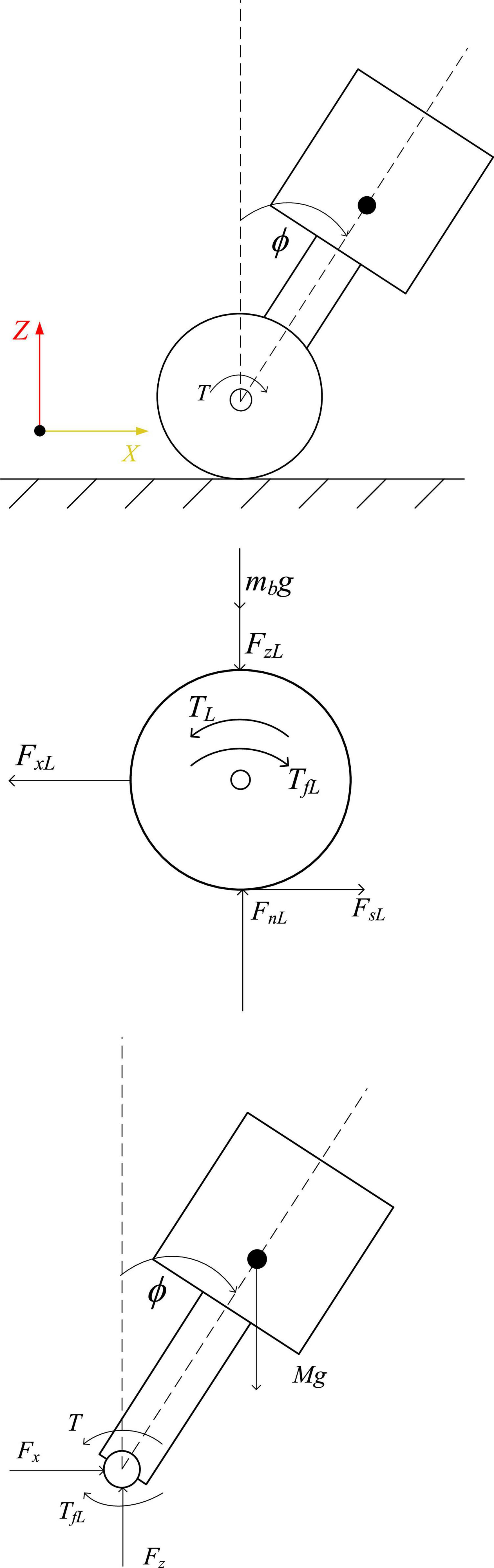
and the positive direction of the X2 axis is φ2 = atan2(2Yc2,2Xc2), the angle between the line of the center of mass c3 and the origin of the coordinate system of and the positive direction of the X3 axis is φ3 = atan2(3Yc3,3Xc3), the angle between the line connecting the center of mass c4 and the origin of the coordinate system of and the positive direction of the X4 axis is φ4 = atan2(4Yc4,4Xc4), the center of mass of the hip motor c5 is at the center of rotation. Let the lengths of the center of mass c1, c2, c3, and c4 from the origin of the , , , and coordinate systems be lc1, lc2, lc3, and lc4, respectively. Then the position of the center of mass of each rod ci relative to the world coordinate system is (Xci, Zci), and the velocity is Xci2.+Zci2., i = 1∼5. Dynamic modeling Self-balancing dynamic modelingWhen the robot maintains a standing posture, the leg linkage mechanism is kept fixed by locking the hip joint motor. At this time, the robot can be equivalent to a two-wheeled self-balancing robot, as shown in Figure 4. The center of mass is located above the wheel axis of the robot, and the pose of the robot in the world coordinate system is [xb,yb,zb,α]T, where the position coordinate of the midpoint of the axis of the driving wheels of the robot is [xb,yb,zb + r], α is the heading angle of the robot, the distance between the centers of the two wheels is D, and the radius of the wheel is r, the angles that the left and right wheels have turned are θL,θR, and the displacements of the left and right wheels are xL,xR, respectively. Assume that the body mass of the simplified robot is M, the length of the body is L, the moment of inertia of the body around the Y axis is Ib, and the position coordinate of the center of mass of the body is [x, 0,z]. The moment of inertia of each connecting rod at the center of mass is Ici, which is obtained with the assistance of Adams simulation software. The tilt angle and body length of the equivalent model are:
Figure 4. Force diagram of equivalent model.
ϕ=arctan(xz-r) ,L=x2+(z-r)2(6)
Taking the left wheel of the robot as an example to analyze the force on the wheel and the body, the balance formula of the force and moment of the body and the wheel can be obtained:
,,,]},,,]},,,]},,,,,]}],"socialLinks":[,"type":"Link","color":"Grey","icon":"Facebook","size":"Medium","hiddenText":true},,"type":"Link","color":"Grey","icon":"Twitter","size":"Medium","hiddenText":true},,"type":"Link","color":"Grey","icon":"LinkedIn","size":"Medium","hiddenText":true},,"type":"Link","color":"Grey","icon":"Instagram","size":"Medium","hiddenText":true}],"copyright":"Frontiers Media S.A. All rights reserved","termsAndConditionsUrl":"https://www.frontiersin.org/legal/terms-and-conditions","privacyPolicyUrl":"https://www.frontiersin.org/legal/privacy-policy"}'>
留言 (0)