
記住我


Globally, stroke is a major threat to human health, and post-stroke care has brought a substantial economic burden to society (Johnson et al., 2019). Due to brain injury, stroke often leads to lower limb dysfunction, which greatly reduces patients' quality of life (Hobbs and Artemiadis, 2020). Therefore, rehabilitation training is needed to help these patients recover their motor function or reduce the risk of several medical consequences secondary to paralysis, such as muscle atrophy and obesity (Chen et al., 2016). In traditional rehabilitation training, the physiotherapist manually guides the patients with impaired limbs to perform repetitive movement training, which is labor-intensive and difficult to quantitatively assess the level of recovery (Akdogan and Adli, 2011). In order to reduce the workload of physiotherapists and enhance the rehabilitation effect, many studies have been conducted on lower limb rehabilitation robots (LLRRs), such as LOPES (Veneman et al., 2007), HAL (Sankai, 2007), and Lokomat (Riener et al., 2005).
Controllers are the critical factor determining the effectiveness of LLRR-aided rehabilitation (Hussain et al., 2013). Among the present research works, most controllers are designed to assist dysfunctional lower limbs in tracking a predefined trajectory (Li et al., 2021). As a model-free controller with a simple and generic control structure, the proportional-integral-derivative (PID) controller has been widely applied to LLRRs (Wu et al., 2015; Zhang et al., 2016; Al-Waeli et al., 2021). However, due to the underutilization of model information, the robotic systems based on the PID controller show poor robustness to external disturbances. Therefore, model-based controllers are proposed to strengthen the anti-disturbance ability of LLRRs. Shen et al. (2020) combined the kinematics and friction models with adaptive robust position control to improve the tracking performance of LLRR under a complex interaction environment. Hernández et al. (2020) designed a non-singular fast terminal sliding mode control for a powered four-degree-of-freedom LLRR, showing strong robustness to external disturbances. Based on a unilateral human-robot dynamical model, a robust controller was designed to drive a LLRR to follow a pre-specified trajectory (Qin et al., 2020). In fact, the LLRR system is characterized by non-linearity, hence the calculation and deduced process of the designed controllers is complicated. Inspired by the triple-step method (Gao et al., 2014; Zhou et al., 2019) proposed a triple-step non-linear controller for LLRR to guarantee control accuracy under different levels of interaction torque. The triple-step method simplified the complicated design of a non-linear controller as a triple-step design process, including the design of steady-state control, feedforward control, and feedback control. On this basis, the structure of the deduced controller was concise.
Dynamic uncertainties of the LLRR system are the main issue that should be considered in controller design (Li et al., 2021). In the LLRR-aided rehabilitation training, the dynamic uncertainties such as human-robot coupling, model uncertainties, and external disturbances, significantly affect the tracking performance. Owing to the non-linear mapping capability, Zhang et al. (2020) combined a radial basis functions neural network (RBFNN) with a sliding mode controller to approach and compensate for the model uncertainties and external disturbances. Besides, Huang et al. (2022) integrated a disturbance observer (DO) into the controller design to compensate for dynamic uncertainties. Khamar et al. (2021) used a non-linear DO in the backstepping sliding controller to assess the wearer's muscle effort and the uncertainties in modeling. Although the control performance of LLRR can be improved by the RBFNN and DOs, the parameters they introduce are difficult to adjust. Long et al. (2017) presented a controller for trajectory tracking under dynamic uncertainties based on active disturbance rejection control (ADRC), which facilitated the parameter tuning. First proposed by Han (2009), the core idea of ADRC is to view the system's external disturbances and internal uncertainties as “total disturbance”, estimate the real-time value of the total disturbance by an extended state observer, and finally compensate for it through feedback to achieve satisfying control performance. Moreover, Gao (2003) proposed a linear version of ADRC (LADRC), i.e., a combination of linear extended state observer (LESO) and linear state feedback, which simplified the control structure and reduced the number of tuning parameters.
Although the LADRC technique is a powerful tool to cope with dynamic uncertainties, extra model information is necessary to further improve the control performance (Li et al., 2022; Long and Peng, 2022). In this paper, a triple-step controller with LADRC (TSC-LADRC) is designed for a LLRR to accurately assist the user in tracking a predefined gait trajectory. On the one hand, the triple-step method establishes the main framework of a model-based controller. On the other hand, the feedback control is modified based on the control conception of LADRC using a second-order error auxiliary system. Accordingly, the total disturbance will be estimated in real time by the LESO and compensated with the feedback control input. To validate the effectiveness of TSC-LADRC, simulations considering the dynamic uncertainties are carried out, and experiments with the LLRR are performed on six healthy subjects. All results show that the trajectory tracking performance under TSC-LADRC is more accurate and robust than that under TSC, especially with different external loads.
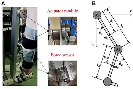
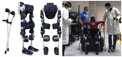
System description Mechanical structureBased on the physiological characteristics of the human's lower limb, we have developed a LLRR with three degrees of freedom, as shown in Figure 1A. The LLRR includes the hip, knee, and ankle joints, where the hip and knee joints of this LLRR are active joints driven by brushless motors (EC 90flat, Maxon, Switzerland) to assist the movement of the wearer's lower limb in the sagittal plane. The linkage is mainly made of lightweight aluminum and nylon materials through machining and three-dimensional printing. Besides, both the thigh and the shank parts are designed as a two-segment mosaic structure that can adapt to subjects of different heights. The wearer's lower limb is fixed to the exoskeleton by Velcro. And the fixed points in the limb are equipped with force sensors (FSSM-500 N, Forsentek, China), which can measure the human-robot interaction forces.
Figure 1. The structure of the LLRR. (A) is the actual prototype of the LLRR. (B) is the simplified two-linkage model of the LLRR.
Since the exoskeleton and the wearer perform motions in a shared workspace, the designed exoskeleton must be safe. According to the ranges of motion for the lower limb exoskeleton (Veneman et al., 2007), once the program detects that the joint angle or speed is out of the normal range, the control system will immediately stop driving the motor. In addition, an emergency shutdown button is set to allow the operator to turn off the motor in time. Mechanical limit plays the ultimate role in protection. Please refer to our previous work for more details (Zhou et al., 2021).
Dynamics modelAs shown in Figure 1B, the exoskeleton can be simplified to a two-link model in the sagittal plane. Considering the external disturbances, joint friction torques as well as the uncertain model parameters, the dynamics of the LLRR can be modeled by the Euler-Lagrange method as follows:
M^(θ)θ¨+C^(θ,θ.)θ.+G^(θ)=τ-T (1) T=τHR+f(θ.)+M(θ)θ¨+C(θ,θ.)θ.+G(θ) (2)Where θ=[θ1;θ2]∈ℝ2 × 1, θ.∈ℝ2 × 1 and θ¨∈ℝ2 × 1 are joint angle, velocity and acceleration vectors, respectively; τ=[τ1;τ2]∈ℝ2 × 1 are the control torques; f(θ.)∈ℝ2 × 1 and τHR∈ℝ2 × 1 are joint friction torques and human-robot interaction torques; M^(θ)∈ℝ2 × 2, C^(θ,θ.)∈ℝ2 × 2 and G^(θ)∈ℝ2 × 1 are the nominal inertia matrix, the nominal centripetal and Coriolis matrix, and the nominal gravitational vector, respectively; M(θ) ∈ ℝ2 × 2, C(θ,θ.)∈ℝ2 × 2 and G(θ) ∈ ℝ2 × 1 are the corresponding model uncertainties between nominal dynamics and actual dynamics; T ∈ ℝ2 × 1 is defined as the total disturbances including the structural and non-structural uncertainties.
The nominal dynamics matrixes are expressed in detail as:
,,,]},,,]},,,]},,,,,]}],"socialLinks":[,"type":"Link","color":"Grey","icon":"Facebook","size":"Medium","hiddenText":true},,"type":"Link","color":"Grey","icon":"Twitter","size":"Medium","hiddenText":true},,"type":"Link","color":"Grey","icon":"LinkedIn","size":"Medium","hiddenText":true},,"type":"Link","color":"Grey","icon":"Instagram","size":"Medium","hiddenText":true}],"copyright":"Frontiers Media S.A. All rights reserved","termsAndConditionsUrl":"https://www.frontiersin.org/legal/terms-and-conditions","privacyPolicyUrl":"https://www.frontiersin.org/legal/privacy-policy"}'>
留言 (0)