
記住我


The soft exosuit system consists of two independent elbow sleeves connected with a shoulder strap and pad to provide elbow support and a control box consisting of inlet valves and pressure sensors (Fig. 1). A snaking tube weaves through the posterior portion of the sleeve so that when pressurized, it provides flexion assistance. In contrast to our previous design [7, 42], the current exosuit has been adapted to incorporate sensors for intention detection, as well as onboard valve-actuation for dynamic control.
Fig. 1
System and experiment methods overview. Hardware. The soft pneumatic exosuit consists of two independent elbow sleeves with actuator tubes that snake through the posterior portion of the sleeves to provide flexion assistance. An air compressor power source is used to inflate the exosuit. Inlet valves and pressure sensors are off-board housed within a separate control box. Outlet valves are located directly on the upper arm at the inlet to the actuator. Inlet and outlet valve opening percentages \(\phi _\) and \(\phi _\) are modulated to control exosuit pressure. Two IMUs per side, ESP32 microcontroller, and battery are embedded in the sleeve to determine exosuit kinematics. High-level control: Decoding intention. A decoded required torque \(\tau _r\) is determined via a gravity compensation scheme (\(\tau _g\)) or a myoprocessor scheme (\(\tau _m\)) based on muscle activity measured with supplementary Delsys EMG sensors. exosuit torque \(\tau _\) being supplied to the wearer is linearly dependent on the actuator tube air pressure. The interaction torque \(\tau _i\) between the exosuit torque provided and decoded torque required from the user should be minimized as much as possible. Low-level control: Optimizing system performance. A PID controller was used to modulate valve opening percentages \(\phi _\) and \(\phi _\) to minimize the interaction torque \(\tau _i\). Neuro-Cognitive Assessment: Tracking task. An EEG study was conducted to determine when the exosuit violated user expectations from the ERP in response to control errors to understand and enhance the cognitive interface with the exosuit
Sensor integrationA single IMU module is placed within the 3D printed housing on the forearm per each side of the exosuit with two modules in total (Fig. 1). Each module is wired to two 9-axis Adafruit BNO055 absolute orientation sensors and contain a ESP-WROOM-32 system on a chip microcontroller, and LiPo battery (3.7 V). The IMU sensors are located in the shin-pad brace on the forearm and upper arm on both sides of the exosuit. The absolute orientation in the form of the quaternion is processed at a rate of 100 Hz from the forearm module, which communicates via Bluetooth serial port to the software system. This sampling frequency limits the refresh rate of the overall closed loop system. The IMU sensors are used to determine the relative orientation in space to get a kinematic model of the upper body in order to infer desired human motion. A predefined calibration position was used to determine the mapping of joint positions of average body limb segment lengths based on average male and female anthroprometric dimensions [43].
The Delsys Trigno EMG system can be seamlessly incorporated with the exosuit system to obtain high quality EMG signals. For all tests using EMG, two electrodes from the Delsys Trigno QUATTRO sensors were positioned on the biceps and triceps according to SENIAM [44] guidelines. The overall hardware of the Delsys system is independent from the current exosuit system and is only required when using the muscle-based control option.
Two pressure sensors are contained within the exosuit control box in series with the inlet air flow into the suit (Fig. 1). They are connected to an ESP-WROOM-32 system on a chip microcontroller housed within the control box. Each pressure sensor measures the pressure within the tube on the left and right side of the exosuit respectively. Monitoring the pressure ensures the device operates within a safe limit, as well as an estimate of the exosuit assistance torque that is being supplied to the wearer.
Pneumatic actuation systemAir flows into the system via a 6mm diameter tube directly connected to an air compressor. The system has the potential to be fully mobile by incorporating a high-pressure air (HPA) tank in place of the air compressor. A safety relief valve is incorporated directly outside the control box to limit the air pressure in the system between 1.5 and 3 bar. Additionally, a low-pressure regulator is used to modulate the input air pressure from the air compressor. The inlet air pressure for device operation was set to 3 bar for all experiments as this provides a suitable system response while minimizing high pressure on the actuator tubes.
The exosuit system contains a valve-actuation sub-system with one inlet and one outlet valve per side of the exosuit (Fig. 1). Both inlet valves are located within the control box between the air compressor and the exosuit tube. Each valve is controlled independently with a servomotor. The two servomotors are connected to the same microcontroller housed in the control box that reads exosuit pressure. The microcontroller communicates with the software system via serial port to control the valve diameter by adjusting the servomotor angle. Outlet valves are located directly on each side of the exosuit near the exosuit tube inlet on the upper arm so that air can be rapidly released when needed. Each outlet valve is connected to the microcontroller and controlled via a servomotor in the same way as the inlet valves. Based on the level of assistance needed, the inlet and outlet valves modulate the amount of air flowing into and out of the system.
Software systemAll sensor information and actuator signals are integrated using the open-source Robotics Operating System (ROS) Kinetic to allow for real-time communication between nodes for exosuit control. Nodes are Python 3 based and run on the Ubuntu 16.04 operating system with the option to become fully mobile in the future. Due to the modularity of ROS, the exosuit can be operated with different control schemes sequentially or in parallel with both arms using a different control method. This provides the option to directly compare control schemes in real-time and then update control based on preferences.
Control systemTwo control schemes based on existing methods were implemented to evaluate and validate performance with the proposed exosuit construction, as well as to enhance ease-of-use for an intuitive user experience. High level control schemes that aim to predict user intentions include gravity compensation and myoprocessor control (Fig. 2). A low-level PID controller was used to optimize the system response to the decoded intention.
Fig. 2
Control system for the soft pneumatic elbow exosuit. \(\mu _\) and \(\mu _\) indicate muscle activations determined from the Delsys Trigno EMG system in the triceps and biceps muscles respectively. \(Q_\) and \(Q_\) indicate the quaternion data collected from the IMU sensors for the upper arm and forearm respectively. \(P_\) is the exosuit pressure reading from the pressure sensor housed within the control box. These sensor readings feed into the high-level control scheme that determines the required torque \(\tau _r\) (gravity: \(\tau _g\) or myoprocessor: \(\tau _m\)), as well as the exosuit torque \(\tau _\). The output of the high-level controller is an interaction torque \(\tau _i\) that acts as an input to the low-level controller. At this stage, the low-level controller aims to minimize the interaction between the user and exosuit assistance by minimizing the interaction torque via a PID controller. The output of the low-level controller is the opening percentages of the inlet valve \(\phi _\) and outlet valve \(\phi _\) respectively which get relayed to the servomotors controlling the inlet and outlet valves for air flow
High-level control: decoding user intentionGravity compensation control An automatic support detection based on a gravity compensation was employed for continuous user control of the exosuit. The level of assistance required is inferred based on the torque about the elbow due to gravity assuming the shoulder angle \(\theta _s\) is 0° with respect to the trunk (Fig. 3). In the case where the shoulder angle is not in line with the trunk, the control scheme still assumes a fixed angle and provides support based on the elbow angle since flexion assistance can only be provided at the elbow joint.
Fig. 3
Schematic of arm model with soft exosuit. The force due to the forearm and hand combined center of mass (\(F_}\)) and the force due to the mass of a held object (\(F_\)) determine the required compensation torque. The perpendicular distance between the elbow joint to the center of mass \(COM_\) is denoted as \(l_c\). The shoulder angle and elbow angle are represented by \(\theta _s\) and \(\theta _e\) respectively
When providing continuous support control, the system should provide assistance such that the system can move naturally with the intended arm movements. The goal is to reduce the interaction torque \(\tau _i\) between user and the exosuit as much as possible such that the exosuit feels for the user as though it is an extension of the body. The high-level control scheme attempts to infer this interaction torque based on the difference between the required torque decoded from the user’s intentions through the gravity compensation control scheme and the existing assistance torque provided by the exosuit.
The assumed gravitational position-dependent torque profile for a decoded required torque \(\tau _r\) is defined as a single joint model:
$$\begin \tau _ = mgl_csin\left( \pi - \theta _e\right) \end$$
(1)
with m as the combined mass of the forearm, hand, and distal part of the exosuit, \(l_c\) the moment arm distance to the center of mass of the forearm and hand based on [43], g the acceleration of gravity, and \(\theta _e\) the elbow angle relative to the shoulder irrespective of the shoulder angle \(\theta _s\).
The exosuit actuators provide flexion assistance, which yields a linear relationship between pressure and assistance torque [7, 42]. Based on this model, the pressure torque relationship can be described by the following equation:
$$\begin \tau _ = \frac\left( r^2 - a^2\right) \end$$
(2)
where \(\tau _\) is the assistance torque, l is the actuator segment length, P is the actuator tube pressure, r is the radius of the tube, and a is the following:
$$\begin a = \left( r + \frac\right) sin\left( \frac\right) \end$$
(3)
with n as the number of segments, w as the distance between two successive housing chambers, and \(\theta \) as the actuator angle.
The interaction torque \(\tau _i\) between the required torque \(\tau _r\) due to gravity and the exosuit assistance torque \(\tau _\) is defined as the difference between the two torques:
$$\begin \tau _ = \tau _ - \tau _ \end$$
(4)
The interaction torque \(\tau _i\) should be minimal for natural arm movements and is thus set to zero for low-level control.
Myoprocessor control To account for various tasks and manipulated objects, an adaptive control scheme dependent on muscle activation may be beneficial. A myoprocessor control scheme based on [5] was implemented to control the exosuit based on intention decoded from muscle activation and arm position. The decoded elbow-flexion torque assumes assistance should be provided to compensate for the immediate effort detected from muscle activation. Therefore, exosuit assistance torque should be provided to compensate for the detected torque from activation of muscles. Since this activation occurs prior to physical movement onset, the exosuit is able to compensate for the predicted torque that would be provided if the exosuit was not present. Thus, the exosuit can account for the decoded torque prior to movement onset for a more adaptable and predictive control scheme. This helps reduce the physical interaction between the user and exosuit device for a more synergistic interface. The myoprocessor control scheme was implemented according to the muscle activation dynamics, a muscle force estimate, muscle kinematics, and muscle dynamics to decode a required torque about elbow.
Muscle activation dynamics A non-linear activation function [20] was used to determine the level of muscle activation in the biceps and triceps:
$$\begin a_j(t) = \frac - 1} \end$$
(5)
where \(a_j(t)\) is the activation of muscle j at time t, \(u_j\) is the EMG RMS envelope at time t, A is the shape factor set to − 1 for a non-linear relationship.
Muscle force estimate The open-source openmuscle Python-based Hill Model implementation [45] based on work by Haeufle et al. [34] was used to determine biceps and triceps force based on EMG activation. The model assumes a three-element configuration with a contractile element, serial non-linear spring element, and parallel non-linear spring element. The estimated muscle response is based on the principle of actin and myosin cross-bridges at the sarcomere level generating muscle force according to the simplified model. Parameters were held constant based on the open-source implementation. An additional gain factor was used to scale the generated force prediction based on user preferences.
Muscle kinematics A simplified muscle moment arm model based on elbow angle determined from cadaveric studies [46] was used to determine the muscle moment arm for torque computation:
$$\begin arm_e(\theta _e) = a_ + 2a_\theta _e \end$$
(6)
with \(arm_e\) referring to both monoarticular elbow flexor (MEF) and extensor (MEE) according to Table 1 that describes the a constants measured.
Table 1 Muscle specific parameters from [46] used for moment arm calculationsMuscle dynamics The overall muscle model combining the muscle force estimate and the muscle kinematics can be described by the following equation in which rapid flexion movements are compensated [34]:
$$\begin \tau _r = l_(\theta _e)F(a_) + l_(\theta _e)F(a_) \end$$
(7)
where \(l_\) and \(l_\) are the moment arms determined from MEF and MEE muscle specific parameters from Table 1 respectively and F refers to the muscle force generated by the respective muscle activation \(a_j\).
This provides an estimate of the torque due to muscle activity and arm kinematics to determine the level of assistance needed to compensate for the required torque decoded. Similar to the gravity compensation control scheme, the required torque decoded is compensated with an exosuit assistance torque through which the interaction torque (Eq. 4) between the two should be minimized with low-level control.
Low-level control: optimizing system responseA simple state machine low-level controller was implemented to get a baseline understanding of the system response. The valves for controlling the exosuit were either set to an open or closed state when the interaction torque \(\tau _i\) was outside of a state threshold \(\tau _\). To refine the control further once within the state threshold \(\tau _\), a PID controller was used to tune opening valve percentage \(\phi _\):
$$\begin \phi _ = \left( \frac - \phi _} - \phi _}\right) \times 100 \end$$
(8)
Here, \(\phi _\) is the set servo angle, \(\phi _\) is the maximum servomotor angle, and \(\phi _\) is the corresponding minimum valve servomotor angle within the desired fully open to fully closed valve range.
A controller threshold \(\tau _\) is used to delineate between two separate PID controllers for the inlet and outlet valves respectively to preserve air in the system for longer operational use. Valves are controlled according to the following conditions:
$$ \left[ c} } \left( } \right)} \\ } \left( } \right)} \\ \end } \right] = \left\l} }\left[ c} 0 \\ 0 \\ \end } \right]} \hfill & } \right| \le \tau _ } \hfill & \hfill & \hfill \\ }\left[ c} } } \\ 0 \\ \end } \right]} \hfill & } > \tau _ > \tau _ } \hfill & \hfill & \hfill \\ }\left[ c} 0 \\ } } \\ \end } \right]} \hfill & } < \tau _ < - \tau _ } \hfill & \hfill & \hfill \\ }state_ } \hfill & } \right| \ge \tau _} } \hfill & \hfill & \hfill \\ \end } \right. $$
(9)
The opening valve percentage of the PID controller is denoted as \(\phi _\) and \(\phi _\) for the inlet and outlet valves respectively. The inlet valve opening percentage range was set between 50 and 80% and the outlet valve opening percentage range was set to 60–90%. This provided a sufficient range to match the decoded torque while limiting the release of air from the system to prolong operational use. When the system exceeds the defined state threshold \(\tau _\), the state machine control scheme takes precedent to return the system back within the state threshold for finer PID control.
User experience: neuro-cognitive assessmentStudy objectivesIn this study, user experience during the interaction with the exosuit was evaluated through a neuro-cognitive assessment. The goal of the experiment was to determine the feasibility of detecting when the exosuit fails to decode intentions and thus violates user expectations. Participants performed a continuous tracking task while operating the exosuit in which EEG, EMG, and kinematic data were recorded to implicitly determine when the exosuit made erroneous actions. By determining when the exosuit behaves in a manner against user expectations, we can understand events in which the trust and expected usefulness, control robustness, ease-of-use, executed actions, and adaptability are affected, thereby diminishing the functional usability of the device [47]. The purpose of the study was to investigate the feasibility of decoding an expectation mismatch when operating the exosuit via the ErrP from EEG signals in a similar approach to previous human–machine interaction studies [36,37,38,39,40]. EMG and kinematic data were also recorded to determine if the motor response could indicate when the soft exosuit exoskeleton violated expectations. With the ability to decode when the exosuit fails to provide assistance according to expectations, the control solution can be updated to reflect user preferences. The secondary objective was to determine whether the exosuit affected control accuracy in the tracking task. For the exosuit to be usable in activities of daily living, it should not impede natural arm movements during operation.
ParticipantsFive healthy subjects between the ages of 20 and 30 (3 male and 2 female) participated in the experiment. All subjects were right-handed and used their right arm for the tracking task. All participants provided written informed consent prior to donning the exosuit. Participants were equally instructed about the experiment paradigm and given practice time to familiarize themselves with the exosuit and experiment task. Subjects were compensated 8 EUR/h for their efforts following the experiment. The study was approved by the institutional ethics review board of the Technical University of Munich under reference number 254/21 S-EB.
Experimental taskSubjects were asked to perform a continuous tracking task while wearing the exosuit to evaluate control and accuracy. An 11 \(\times \) 6 grid with a motion trajectory was displayed for subjects to follow with a cursor based on arm movements (Fig. 4A). Visually, participants saw the goal trajectory to follow and the cursor position mapped to wrist position calculated from the inverse kinematics of the exosuit (Fig. 4C). Once subjects reached the goal trajectory, a new tracking episode appeared with this process repeating until the experiment block was complete. Subjects performed the tracking task in an unassisted and assisted state with both gravity compensation and myoprocessor control schemes split up by experiment blocks. While participants performed a continuous tracking task, exosuit action events were generated by discretizing the cursor movement between grid spaces. During error blocks only, the experiment initiated purposeful control error events to determine if the errors could be detected from the brain and motor response based on the unexpected behavior. Control errors consisted of providing unnecessary assistance or releasing assistance at random steps within the grid trajectory. To avoid habituation to erroneous exosuit actions, control errors were introduced at a rate of 30% of total events in error blocks only [36], beginning at the moment when the tracked cursor moved fully into the next grid space. The introduction of artificially created errors mimicks the situation of an exosuit failing to correctly interpret the user’s intention. This provides the opportunity to posthoc validate the performance of decoding these events from the passive neural and motor response.
Fig. 4
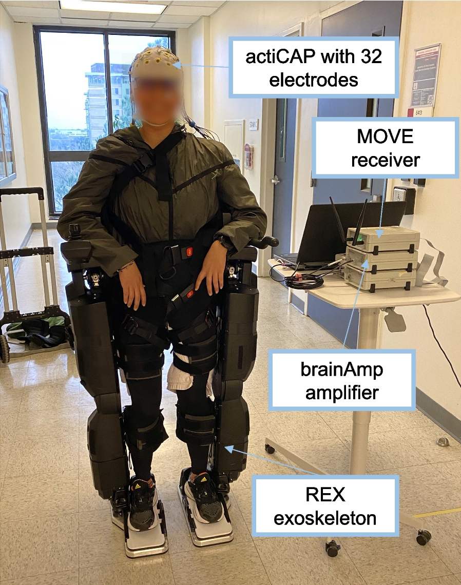
User experience: Neuro-cognitive assessment experiment setup. A Example of a single episode showing the grid layout with a goal trajectory for subjects to track cursor with corresponding arm movements. B Subject wearing soft exosuit sitting in a chair facing the monitor displaying the experiment. The subject is wearing an EEG cap with 32 active gel-based electrodes for measuring neural activity. In this part of the experiment, the subject is controlling the cursor through the grid trajectory. C The Delsys Trigno EMG system with two electrodes from the QUATTRO sensor is used to record EMG data from biceps and triceps muscles respectively. The wrist position determined from the inverse kinematics from the IMU sensors is used to map the cursor position on the screen in the task. A full range of motion was required to move the cursor throughout the entire grid, with the arm needing to reach fully flexed and extended positions from medial to lateral-right side of the body
Stimuli and apparatusExperimental setup Subjects were seated directly across from a LCD 42” standing monitor that displayed the experiment paradigm full-screen (Fig. 4B). Participants were fitted with the soft exosuit so that they were comfortable and understood how the device operates. Prior to using exosuit assistance, subjects were instructed to move naturally while wearing the exosuit to get a feel for how it passively moves with arm motions. We ensured subjects operated the exosuit safely and were comfortable by having them state they were ready prior to proceeding with the experiment. Throughout the experiment, subjects were instructed to relax as much as possible when performing arm motions. The air compressor was filled at the beginning of the experiment and was refilled after every third block to ensure the exosuit was properly pressurized throughout the entire experiment.
EMG data acquisition The Delsys Trigno EMG system with QUATTRO sensor was used for EMG recording throughout the entire experiment and exosuit control during the myoprocessor control scheme blocks. Two leads of the QUATTRO sensor were placed on the biceps and triceps respectively according to SENIAM guidelines [44] with the reference electrode on the side of the forearm (Fig. 4C). EMG sensors were wirelessly connected to the Delsys Trigno hub so that subjects were free to move their arm in space. An EMG recording ROS node integrated the EMG signal for exosuit control and synchronized it with events from the experiment. The raw EMG signal was collected at a rate of 2222 Hz and bandpass-filtered between 20 and 450 Hz. From a sliding window of 100 ms width, the Delsys transmitters computed the RMS signal at a rate of 222 Hz which was used for both control and measurement during the experiment.
EEG data acquisition and preprocessing EEG data was recorded using the Brain Products actiChamp system. Subjects wore an EEG cap with 32 active gel-based electrodes arranged according to an extended international 10–20 system [48] (FP1, FP2, F3, F4, F7, F8, FC1, FC2, FC5, FC6, C3, C4, T7, T8, CP5, CP6, P3, P4, P7, P8, TP9, TP10, O1, O2, Fz, Cz, Pz, EOG1, EOG2, EOG3). The mastoid electrodes TP9 and TP10 were used as the reference for all leads. Impedances for all electrodes were kept below 15 k\(\Omega \) per subject and the signals were recorded with a sampling rate set at 1000 Hz. Electrooculogram (EOG1–3) signals were captured by three electrodes located on the subject’s forehead, left and right outer canthi according to Schlögl et al. [49]. The EEG amplifier was powered by a battery and connected to the recording PC located adjacent to the experiment area. The recording PC was connected via parallel port to the PC running the experiment for synchronously recording event triggers with the EEG data.
Experiment protocolThe overall experiment consisted of 15 blocks in total with 8 episodes per block. An episode consisted of 10–15 movement events depending on the length of the randomly generated trajectory. Each exosuit movement event was considered to be a single trial in the subsequent analysis of ERPs. The total duration of the experiment took approximately 45–60 min including breaks. A summary of the experiment protocol with the corresponding control schemes and error rates is shown in Table 2. Prior to beginning the experiment, subjects first conducted a drawing practice session in which they controlled a cursor on the screen to draw with arm movements. This ensured participants understood how the device moved with intended arm movements and the exosuit-to-cursor mapping on the screen. This practice session was repeated before beginning a block with a new control scheme. Participants were asked if they felt comfortable with the new control scheme before proceeding to the next experiment phase.
Table 2 Summary of the experimental protocolData analysisTrajectory accuracy Trajectory accuracy was evaluated within non-error blocks. It was measured by taking the total number of correct trials out of the total number of trials of the goal trajectories. This measure for each control scheme was compared to a baseline measure of accuracy in the unassisted condition.
EEG analysis Data preprocessing was carried out in MATLAB using the EEGLAB toolbox [50] and used the same procedure as the study by Ehrlich and Cheng [40]. The EEG and EOG signals were filtered using a zero-phase Hamming windowed sinc FIR bandpass filter between 1 and 20 Hz. Contaminated channels were determined using kurtosis with a 5% threshold and correspondingly interpolated. Eye blinks were corrected via the EOG signals based on Schlögl et al. [49]. All electrodes were re-referenced to a common average reference of all channels to further reduce noise in the signal.
Single trial ERPs were epoched time-locked to the onset of movement beginning when the cursor was fully contained within a grid space at which point the grid space changed color to a darker shade of green for a correct step (Fig. 4B). Epochs began at the event-onset and ended one second post step-onset to account for the varying speed at which subjects moved the cursor. In error blocks within the respective control scheme, trials were grouped based on whether or not a control error was present. Pearson correlation across the negative deflection from 300 to 400 ms post-event onset was determined between trials in different control schemes for a similarity measure.
For classification of errors, temporal features were selected by first downsampling the epochs to 125 Hz and selecting a sub-set of channels of interest, namely Fz, F3, FC1, C3, Cz, C4, T8, FC6, FC2, F4, and F8 for approximately 200 features per event. Channels were selected based on feature discriminability and expected spatial location of neural response based on insights provided by earlier works on decoding ErrPs [36, 39]. Dimensionality reduction was then performed to extract latent features through principal component analysis (PCA) to increase the separability of features based on variance. The temporal features were evaluated using a Fisher score analysis to determine the discriminative power. Subsequently, a regularized linear discriminant analysis (rLDA) classifier based on [51] was used to discriminate events based on the labeled overall groupings of control error and non-error trials. The regularization aims to minimize the covariance estimation error by penalizing small and large scalings of the hyperplane discriminating the feature space. This classifier was chosen based on success in previous BCI works in the decoding of ErrPs [39, 40]. The classification problem between control error trials and non-error trials was validated with a tenfold cross validation. For each subject, trials were randomly split into tenfolds with ninefolds used for model calibration and the remaining fold for testing. This procedure was repeated ten times in total for an estimate on how well a subject-specific decoder would perform on unseen data within a single session. Classification results per subject are reported as the average percentage of correctly classified trials across all folds. This provides a subject-specific decoder accuracy of detecting unexpected exosuit actions based on user perceptions.
EMG analysis The preprocessed RMS signal was used to determine EMG muscle activation of both biceps and triceps muscles. The signal was epoched and grouped using the same method as the EEG analysis. Epochs began 0.2 s before event onset and continued for 1.5 s after the event beginning. Temporal RMS features from biceps and triceps channels were extracted and subsequently reduced dimensionally using PCA. Classes were grouped based on error and non-error trials in the error-blocks. The classification problem was handled identically to the EEG classification analysis with a rLDA classifier and tenfold cross validation to report overall EMG model accuracy for correctly predicting error events based on EMG activity.
Kinematic analysis The angular velocity of the elbow joint was also measured to determine when subjects experienced rapid changes in elbow flexion or extension. Trials were epoched according to the same procedure as the EEG and EMG data analysis with trials consisting of control errors and non-errors. The raw elbow angular velocity was reduced dimensionally using PCA. The identical classification procedure as the EEG and EMG analysis (rLDA classifier and tenfold cross validation) was used to classify error trials based on kinematic data.
StatisticsTukey honestly significant difference (HSD) tests were used to determine EEG channel regions of significant difference between error and non-error trials. Additionally, a Tukey HSD test was used to cross-compare the unassisted, gravity, and myoprocessor control conditions with respect to trajectory accuracy. Group decoding accuracy distributions were tested with the Lilliefors test to determine normality. Paired t-tests were used to compare decoding accuracy between control schemes across the different modalities. A power analysis was conducted to determine the minimum number of subjects needed for significant difference. Statistical testing was conducted using Python 3.7 with SciPy and Statsmodels packages. Error bars indicate mean ± standard error of the mean (SEM) in Fig. 5.
Fig. 5
Neuro-cognitive assessment results A Grand average ERP response in channel Cz from all subjects combining gravity and myoprocessor control schemes for error vs. non-error trials in error blocks. Difference represents the difference between error and non-error trials. The response during the unassisted blocks is shown as a reference. Topographic visualizations of the difference between error and non-error trials in error blocks for gravity and myoprocessor control schemes respectively are shown below the ERP time-course plot. Regions outlined show areas of significant difference from Tukey HSD tests with \(p<0.05\). B Grand average motor response (biceps, triceps, and elbow angular velocity) from all subjects grouped by control scheme for error vs. non-error trials in error blocks. C Classification results from user experience neuro-cognitive assessment study. Trained rLDA models based on signals from EEG, EMG, and elbow angular velocity were used to classify control error trials during error blocks. The gravity and myoprocessor (Myo) control methods were compared to determine if accuracy was affected based on the control measure. Additionally, a combined accuracy for both control methods was determined per model. Error bars indicate mean ± SEM across subjects per model and control scheme. Representative confusion matrices for the combined control scheme models from subject 1 are depicted beneath the group results
留言 (0)