
記住我
There are different schools of thought concerning positioning of a total knee arthroplasty (TKA). The most popular school references the mechanical axis of the lower limb for all patients.1,2 Another uses kinematic axis alignment (KA), an individualized anatomical approach often performed with caliper measurements to cut equal bone resections from the joint surfaces, which aims to restore native joint line anatomy and orientation.3 And most recently, functional alignment (FA) has been developed as a technique to restore native joint line height and obliquity and utilizing ligament tension assessed by using computer-assisted technology to guide bone resections and implant position.4,5 The goal of FA is to implant TKA components in the position that restores the plane and obliquity of the joint and minimizes any damage to soft tissues. FA differs from KA because KA can be executed with a calipered technique and KA lacks quantitative measurements of the soft tissue situation.5,6 Alignment to bony anatomy and soft tissue balance have always been important for success in TKA.1 In FA, soft tissue balance dictates final position of components rather than bony resection depths.
A FA technique was first described in 2018 in a cadaveric video article,7 and the term “functional” was then associated with it in 2020.5 In a patient series, FA has only been described with an initial mechanically aligned plan.4 The components were then adjusted to balance the soft tissues. Although potentially recreating joint line height, this does not replicate native joint line obliquity. For example, in Figures 1 and 2 we show the same knee with a native 3 degrees valgus femur and 6 degrees varus tibia. Using a mechanical preoperative plan, shown in Figure 1A, from which to balance, the final functional implant position will be a neutral femur and a 3 degrees varus tibia (Fig. 1B). Alternatively, in the same knee if a surgeon were to use a plan with equal resections distally and posteriorly on the femur from which to balance (Fig. 2A), the final implant position would result in a 6 degrees varus tibia and a 2.4 degrees valgus femur with joint line obliquity similar to the native knee (Fig. 2B).
 FIGURE 1: Two screenshots of (A) a prosthesis (shown in green) aligned to the mechanical axis relative to a patient’s knee model from computed tomography scans and (B) a final functional mechanical plan after the surgeon adjusted the implant to achieve balanced gaps. Initial gaps from the mechanical plan were 20 mm medial extension, 22 mm lateral extension, 17 mm medial flexion, and 22 mm lateral flexion. From this plan, balance could be achieved with 20 mm gaps by locking the medial? tibia to add 3 varus and locking the lateral? femur to add 3.5 degrees external rotation. Starting with a mechanical plan results in a different functional alignment final plan than if a surgeon started with a kinematic axis alignment plan (Fig. 2). Final achieved gaps in this case were 20 mm medial extension, 20 mm lateral extension, 20 mm medial flexion, and 20 mm lateral flexion.
 FIGURE 2: A, An initial kinematic preoperative plan. B, Final component position using the described technique. When max stresses were applied to the knee shown in Figure 1A with a kinematic axis alignment initial plan, we found the following gap numbers: 23 mm medial extension, 23 mm lateral extension, 20 mm medial flexion, and 23 mm lateral flexion. From this plan, we can achieve 20 mm gaps by moving the tibia proximal 3 mm and locking the lateral femur to apply 4 degrees external rotation. Final achieved gaps were 20 mm medial extension, 20 mm lateral extension, 20 mm medial flexion, and 20 mm lateral flexion.
There is increasing evidence supporting an individualized TKA alignment target that considers a patient’s unique constitutional alignment and joint line obliquity.8,9 Therefore, the purpose of this paper is to describe a surgical technique for achieving FA and all of its defined elements.
MATERIALS AND METHODSAll patients included in this study were consented to participate in an Institutional Review Board-approved prospective clinical registry for data collection and publication purposes.
Indications and ConsiderationsThis FA technique was indicated for primary TKA in osteoarthritis and inflammatory arthritis and has been performed by a single surgeon (G.W.C.) in a consecutive series of 650 TKAs. From this experience, relative contraindications include severe valgus knees, fixed flexion deformity >20 degrees, extra-articular deformity, and previous realignment osteotomy of the knee. This technique should not be performed in patients with collateral ligamentous deficiency. This technique, whilst intended predominantly for cruciate-retaining designs, can be used with posterior-stabilized TKA. Large posterior osteophytes were a relative contraindication which may lead to the requirement for recuts at the trialing stage.
Preoperative PlanningA preoperative supine computed tomography (CT) scan was collected in preparation for robotic-arm assisted surgery using the Mako Total Knee application (Stryker, Kalamazoo, MI). The scan was then segmented to render a 3-dimensional model. CT landmarks were mapped, with tibial rotation set to Akagi’s line.10 Resection points were mapped to the most prominent point of the distal femoral condyles and the most posterior point of the posterior femoral condyles avoiding osteophytes. The tibial resection points were placed at the midpoint of each plateau two-thirds posteriorly in the anteroposterior plane.
An initial implant position was established following the principles of KA, which uses equal bony resection depths to establish the native joint line position and obliquity, from which balance was then assessed and adjusted to achieve FA (Fig. 2). Resection depths were set to 6.5 mm on both medial and lateral distal femoral condyles (max 6 degrees valgus) and 6.5 mm resection on both medial and lateral posterior femoral condyles. The target of 6.5 mm resections on the femur was based on 6.5 mm bone plus 2 mm cartilage being 8.5 mm, which was the distal thickness of the femoral component (Stryker) used in this technique, to restore the joint line. On the tibia, 7 mm resections were set both medially and laterally (maximum 6 degrees varus), based on subchondral bone and an average cartilage depth of 2 mm in the normal knee,11 to use a 9 mm polyethylene insert. If the hip-knee ankle angle (aHKA), which was calculated as the sum of the femoral coronal alignment (varus/valgus) and the tibial coronal alignment (varus/valgus),12 fell outside of 6 degrees varus to 3 degrees valgus, we altered the tibial coronal alignment until aHKA fit within this window. The recommended guidelines for preoperative implant positioning is shown in Table 1, and all TKAs in this series were preoperatively planned within these boundaries.
TABLE 1 - Preoperative Implant Positioning Guidelines Recommended Parameter Boundary aHKA 6 degrees varus to 3 degrees valgus Femoral coronal 6 degrees valgus to 3 degrees varus Femoral rotation From PCA to 5 degrees ER to TEA Femoral flexion Up to 7 degrees, with no more than 10 degrees combined flexion Tibial coronal 6 degrees varus to 3 degrees valgus Tibial rotation From 5 degrees IR-5 degrees ER to Akagi’s line Tibial slope Up to 8 degrees slopeaHKA indicates hip-knee ankle angle; ER, external rotation; IR, internal rotation; PCA, posterior condylar axis; TEA, trans-epicondylar axis.
Implant sizing was then checked preoperatively on the CT scan. We sized the tibia with rotation to 0 degrees on the axial view achieving maximal cortical contact with minimal overhang. We then adjusted tibial slope to best match the lateral tibial plateau, with the goal of achieving more natural kinematics with a soft tissue generated medial pivot. The medial side was stabilized between the posterior cruciate ligament and medial collateral ligament and balanced throughout the range-of-motion and as such had minimal translation in the anteroposterior plane. It was for this reason the medial slope was considered less important than the lateral slope where there was expected translation. For the femur, we started with same size as the tibia (usually same size or 1 smaller). We adjusted femoral flexion around the radius of curvature of the femoral component (as this will not alter resection depths) until the anterior cut exited the anterior femoral cortex within 5 mm of the tip of the implant. Femoral flexion was within 0 to 7 degrees flexion, and combined flexion did not exceed 10 degrees, which was the defined implant limit for combined flexion to prevent impingement in full extension. If it was not possible to keep femoral flexion between 0 and 7 degrees flexion, femoral component size was adjusted. If there were 2 sizes that could fit, we chose the size that best replicated the femoral radius.
Surgical StepsThis technique used a cruciate-retaining TKA implant design (Triathlon Total Knee System; Stryker) and the Mako robotic-arm assisted surgery system (Stryker). Extra-articular pins were applied to the femur and tibia (10 cm proximal to superior pole of the patella at 90 degrees flexion and 10 cm distal to the tibial articular surface). Surgery was standardized with a midline skin incision and medial parapatellar approach. Registration with an optical probe was undertaken to inform the robotic system of femoral and tibial positions relative to the trackers in 3 dimensions (Fig. 3). Once registration was checked and verified, osteophytes were removed where possible and the ACL resected. If using a posterior cruciate sacrificing implant, the posterior cruciate ligament was resected at this point. An assessment of maximal stressed virtual gaps was made utilizing the Mako software (Mako TKA 1.0 software; Stryker) and was recorded. This was performed at 10 degrees flexion (to de-tension posterior capsule and minimize the effect of posterior osteophytes) and 90 degrees flexion.
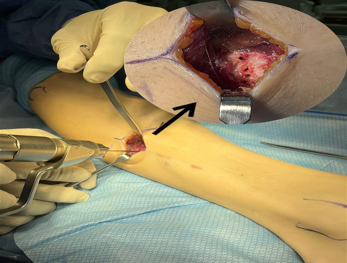
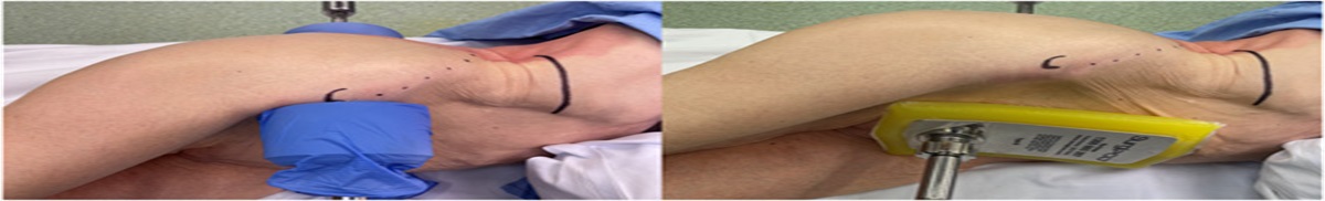
 FIGURE 3:
 An intraoperative photo showing the trackers positioned on the lower limb before total knee arthroplasty.
Methods for obtaining gap values included manual stressing, distraction spoons/periosteal elevators and lamina spreaders. The author’s preferred method was varus/valgus manual tensioning as this was how balance was assessed at completion of the TKA. Four gap numbers were collected and were used to balance a TKA: (1) maximum medial extension gap; (2) maximum lateral extension gap; (3) maximum medial flexion gap; and (4) maximum lateral flexion gap (Fig. 4). Once maximal virtual gaps were obtained, component position was adjusted until the knee was balanced on the Mako software. The extension gaps were balanced first as this resulted in less coronal implant variation from the native tibia or femoral joint line. First, if there was obvious bone loss then the resection depth was reduced on that condyle to better replicate the native joint line. Maximal extension gaps were balanced to 20 mm medially and laterally by altering resection depth and position of the tibial component. We recommend moving the femoral component only if extension balance cannot be achieved by adjusting the tibia within the recommended limits (Table 1). In the majority of knees, there was tightness on the medial side. By maintaining femoral position to the joint line, we avoided increasing medial resection on the femur, decreasing joint line obliquity and putting relative varus on the femoral component. If balance could not be achieved within an overall limb alignment of between 6 degrees of varus and 3 degrees of valgus, the more lax side was balanced to 20 mm and the tighter side was set as close to 20 mm as possible accepting a soft tissue release was likely to be required. From our experience, this occurred in 25 of 650 (3.8%) TKAs (Table 2).
 FIGURE 4:
 This figure shows virtual ligament balancing pages when max stresses are applied across the joint with implants in kinematic alignment. When a max varus force is applied to the knee in extension (A), the max gap is 22 mm on the medial side and when a max valgus force is applied in extension (B), the max gap is 22 mm on the lateral side. When a max varus force is applied to the knee in flexion (C), the max gap is 20 mm on the medial side and when a max valgus force is applied in flexion (D), the max gap is 23 mm on the lateral side.
TABLE 2 - Soft Tissue Releases Performed for Coronal Balance in 650 TKAs Number Type Medial 3 3 MCL needle-fenestration releases Lateral 22 10 LCL needle-fenestration releases 6 with lateral retinaculum release 2 with ITB release 2 no other releases specified 6 LCL surgical releases 3 with ITB release 3 with no other releases specified 3 ITB releases without other releases 3 Popliteus releases 1 with partial PCL release 2 with no other releases specifiedITB indicates ilio-tibial band; LCL, lateral collateral ligament; MCL, medial collateral ligament; PCL, posterior cruciate ligament; TKA, total knee arthroplasty.
After balancing the extension gaps, the medial flexion gap was adjusted until it was equal to the medial extension gap. This was achieved by rotating the femoral component from the posterior lateral femoral condyle. Caution should be used if internally rotating the femoral component to the posterior condylar axis as this was rarely required and usually represented poorly captured gap measurements. The lateral flexion gap in all TKAs was no less than the medial flexion gap. But in this technique we accepted if the lateral flexion gap remained looser than the medial side when the lateral posterior condyle was being anatomically resected, in an attempt to recreate the native lateral flexion gap which was variable.13 This together with replicating the lateral tibial plateau slope was designed to enable more natural kinematics with a stable medial side and lateral translation as dictated by the soft tissues. If using a posterior-stabilized TKA, we targeted equal flexion gaps to prevent gapping on the lateral side with a loose lateral flexion gap.
The virtual gaps obtained in this method were designed to accommodate the implant design. The femoral component used was 8.5 mm thickness and the tibial component, with the thinnest insert, was 9 mm thickness. A laxity of 1 to 2 mm was required to have the knee balanced to the tension considered by the authors as optimal. The exact laxity required in TKA has not been definitively determined and is an area of future research. The knee system used in this technique has 1 mm incremental polyethylene insert thicknesses and hence aiming for a 20 mm gap often resulted in the use of a 10 mm insert but the gaps were never too tight to be able to fit the 9 mm insert as the robotic system has been shown to be accurate to within 1 mm on each of the cuts.14 By this method soft tissue tension was used to determine the final overall limb alignment, rather than the plan obtained from bony anatomy.
Before executing the bone cuts a final review of planned implant and limb positions was undertaken to ensure the steps taken to balance the knee did not result in final implant alignment outside of 6 degrees valgus to 3 degrees varus for the femoral component, 6 degrees varus to 3 degrees valgus for the tibial component, and 6 degrees varus to 3 degrees valgus for overall aHKA.
The robotic-arm was then moved into position and the arm was again validated. All 6 bone cuts were then performed. The distal femoral cut and posterior chamfer were performed with the 90 degrees saw blade. This was then changed to the straight blade attachment and the posterior, anterior and anterior-chamfer cuts were made on the femur and then the tibial cut was executed. Bone fragments were removed, as well as menisci and posterior osteophytes. Trial implants were then inserted with a 9 mm trial insert, and maximal gaps were then obtained with trial components in place utilizing the ligament balancing page on the Mako software. Medial and lateral gaps in extension were within 1 mm of each other as was the medial flexion gaps. If imbalance existed, then either recuts were made or soft tissue release were performed, with a preference for the bone recut. We performed 2 tibial recuts in our series of 650 TKAs (0.3%). The final insert size was determined by surgeon’s assessment of sagittal stability, ability to achieve full extension and collateral ligament tension. Either a cruciate-retaining or cruciate-stabilizing insert can be used with this technique. Once satisfied with the balance of the trials, the patella was resurfaced in all TKAs. Final components were then inserted with the author’s preference for uncemented components, but cemented components can also be utilized.
BRIEF RESULTSThe described FA technique has been performed in a single surgeon’s consecutive series of 650 TKAs. A summary of final target alignment for 650 TKAs is shown in Table 3 and in Figure 5. The coronal femoral component alignment target was mean 2.4 degrees valgus (±2 degrees STD) and coronal tibial component alignment target was mean 4.2 degrees varus (±2 degrees STD). Mean overall aHKA target was 1.8 degrees varus (±3 degrees STD). Soft tissue releases were executed in 25 TKAs (3.8% of 650 TKAs). The types of releases performed are shown in Table 2.
TABLE 3 - Final Functional Alignment Implant Position Executed in 650 TKAs Parameter Mean (range) aHKA 1.8 degrees varus (6.5 degrees varus to 4.6 degrees valgus) Femoral coronal 2.4 degrees valgus (3.1 degrees varus to 7.9 degrees valgus) Femoral rotation to TEA 0.1 degrees IR (6.9 degrees IR to 6 degrees ER) Femoral flexion 3.0 degrees (2.5 degrees extension to 8 degrees flexion) Tibial coronal 4.2 degrees varus (6.4 degrees varus to 3.7 degrees valgus) Tibial rotation to Akagi’s line −0.1 degrees (2.7 degrees IR to 3.6 degrees ER) Tibial slope 3.6 degrees posterior slope (0 to 8 degrees)aHKA indicates hip-knee ankle angle; ER, external rotation; IR, internal rotation; TEA, trans-epicondylar axis; TKA, total knee arthroplasty.
 FIGURE 5:
 Histograms of (A) femoral coronal alignment, (B) tibial coronal alignment and (C) hip knee ankle angle alignment in 650 total knee arthroplasties after using the described technique for functional alignment.
We collected 2-year postoperative outcome data on 165 TKAs of 193 TKAs (85% follow-up) that have reached this time point (193 TKAs in the series of 650 TKAs are now 2 y postoperatively). Patient demographics for these 165 TKAs are shown in Table 4. We found significant postoperative improvements with few infections and no revisions for mechanical reasons 2 years after surgery with this technique. Patients had improved knee range-of-motion (105 degrees flexion preoperatively vs. 125 degrees flexion postoperatively; P<0.001), higher Forgotten Joint Scores (17 preoperatively vs. 77 postoperatively; P<0.001), improved Oxford Knee Scores (22 preoperatively vs. 43 postoperatively; P<0.001), higher KOOS Jr Scores (48 preoperatively vs. 88 postoperatively; P<0.001) and lower visual analogue score pain scores (70 preoperatively vs. 12 postoperatively; P<0.001). The reported complications in the entire series of 650 TKAs performed with this technique are described in Table 5.
TABLE 4 - Patient Demographics and Characteristics for 165 TKAs With 2-year Follow-up Characteristic Mean age, years (range) 67±8 y (46-91) Sex ratio, males: females, n 72:93 (56% female) Side, left:right, n 83:82 Body mass index, kg/m2 32 (range: 18-51) Mean preoperative aHKA angle (range) 1 degrees varus (10 to 11 degrees valgus) Mean preoperative LDFA angle (range) 87±3 degrees (79-93 degrees) Mean preoperative MPTA angle (range) 86±3 degrees (79-91 degrees)aHKA indicates hip-knee ankle angle; LDFA, lateral distal femoral angle; MPTA, medial proximal tibial angle; TKA, total knee arthroplasty.
DAIR indicates debridement and implant retention; TKA, total knee arthroplasty.
KA has emerged as a potential solution for some patients undergoing TKA.15,16 FA further refines alignment from a KA position, to not only account for bony anatomy but also soft tissue balance. The present study shows a novel approach for achieving FA during robotic-assisted surgery. One other paper has previously described a similar technique, but had very limited patient follow-up (reported on 2 patients with 3 mo follow-up).7 To our knowledge, this is the first paper to report 2-year outcomes with this surgical technique. Benefits of this approach include improved efficiency with preresection balancing, fewer soft tissue releases, and accurate execution of bony cuts with robotic assistance.4,7,14 Our results are promising with excellent patient outcomes and few complications in comparison with other knee series using mechanical and kinematic alignment and in comparison with other studies reporting on Triathlon TKAs.16–18 These results do not have a comparator with respect to alignment philosophy nor surgical technique and as such cannot be considered to be superior to any other results in the literature.
Alignment philosophies continue to evolve as surgeons learn more about the knee anatomy from 3D imaging and receive quantitative real-time balancing feedback from navigation and robotic platforms in the operating room. The FA technique we describe positions implants relative to a patient’s unique constitutional alignment, prioritizing femoral anatomy which has been shown to be important for knee kinematics.19,20 It may feel unnatural for patients with oblique joint lines to have TKAs aligned to the mechanical axis, since this change in knee alignment will affect soft tissue tension around the knee as well as the overall contact forces through the hip and ankle as well.8,21 There is increasing evidence supporting an individualized TKA alignment target, since there is variation in knee alignment in the general population,8 and studies are reporting similar long-term survivorship of TKAs that have been mechanically aligned (0±3 degrees relative to the mechanical axis) and those outside that range.15,22 But what the appropriate target is for every patient continues to be debated. Randomized controlled trials are currently underway using the robotic-arm system described in this technique to test the impact of alignment on patient outcomes.23
CONCLUSIONSA well-balanced knee can be achieved by surgeons in many ways. In both M.A. and K.A., the correct sequence of soft tissue releases to allow the soft tissue envelope to adapt to the position of a TKA is required,1,24 while in FA there is a need for technological aides and accurate execution to adjust the position of the TKA to a balanced position within the soft tissues. Longer-term data is required to demonstrate the appropriate target for individualized limb alignment.5 We do not present this FA technique as a definitive method of robotic TKA. Nonetheless, we believe that this technique should be considered as a means for conducting a robotic TKA.
REFERENCES 1. Insall J, Scott WN, Ranawat CS. The total condylar knee prosthesis. A report of two hundred and twenty cases. J Bone Joint Surg Am. 1979;61:173–180. 2. Moreland JR, Bassett LW, Hanker GJ. Radiographic analysis of the axial alignment of the lower extremity. J Bone Joint Surg Am. 1987;69:745–749. 3. Howell SM, Howell SJ, Kuznik KT, et al. Does a kinematically aligned total knee arthroplasty restore function without failure regardless of alignment category? Clin Orthop. 2013;471:1000–1007. 4. Chang JS, Kayani B, Wallace C, et al. Functional alignment achieves soft tissue balance in total knee arthroplasty as measured with quantitative sensor-guided technology. Bone Jt J. 2021;103-B:1–8. 5. Oussedik S, Abdel MP, Victor J, et al. Alignment in total knee arthroplasty. Bone Jt J. 2020;102-B:276–279. 6. Howell SM. Calipered kinematically aligned total knee arthroplasty: an accurate technique that improves patient outcomes and implant survival. Orthopedics. 2019;42:126–135. 7. Calliess T, Ettinger M, Savov P, et al. Individualized alignment in total knee arthroplasty using image-based robotic assistance: video article. Orthopade. 2018;47:871–879. 8. Bellemans J, Colyn W, Vandenneucker H, et al. The Chitranjan Ranawat award: is neutral mechanical alignment normal for all patients? The concept of constitutional varus. Clin Orthop. 2012;470:45–53. 9. MacDessi SJ, Griffiths-Jones W, Harris IA, et al. Coronal Plane Alignment of the Knee (CPAK) classification. Bone Jt J. 2021;103-B:329–337. 10. Akagi M, Oh M, Nonaka T, et al. An anteroposterior axis of the tibia for total knee arthroplasty. Clin Orthop. 2004:213–219. 11. Shepherd D, Seedhom B. Thickness of human articular cartilage in joints of the lower limb. Ann Rheum Dis. 1999;58:27–34. 12. MacDessi SJ, Griffiths-Jones W, Harris IA, et al. The arithmetic HKA (aHKA) predicts the constitutional alignment of the arthritic knee compared to the normal contralateral knee: a matched-pairs radiographic study. Bone Jt Open. 2020;1:339–345. 13. McEwen P, Balendra G, Doma K. Medial and lateral gap laxity differential in computer-assisted kinematic total knee arthroplasty. Bone Jt J. 2019;101-B:331–339. 14. Sires JD, Craik JD, Wilson CJ. Accuracy of bone resection in MAKO total knee robotic-assisted surgery. J Knee Surg. 2021;34:745–748. 15. Klasan A, de Steiger R, Holland S, et al. Similar risk of revision after kinematically aligned, patient-specific instrumented total knee arthroplasty, and all other total knee arthroplasty: combined results from the Australian and New Zealand Joint Replacement Registries. J Arthroplasty. 2020;35:2872–2877. 16. McEwen PJ, Dlaska CE, Jovanovic IA, et al. Computer-assisted kinematic and mechanical axis total knee arthroplasty: a prospective randomized controlled trial of bilateral simultaneous surgery. J Arthroplasty. 2020;35:443–450. 17. Young SW, Walker ML, Bayan A, et al. The Chitranjan S. Ranawat Award : no difference in 2-year functional outcomes using kinematic versus mechanical alignment in TKA: a randomized controlled clinical trial. Clin Orthop. 2017;475:9–20. 18. Roussot MA, Vles GF, Oussedik S. Clinical outcomes of kinematic alignment versus mechanical alignment in total knee arthroplasty: a systematic review. EFORT Open Rev. 2020;5:486–497. 19. Eckhoff DG, Dwyer TF, Bach JM, et al. Three-dimensional morphology of the distal part of the femur viewed in virtual reality. J Bone Joint Surg Am. 2001;83-A(suppl 2):43–50. 20. Eckhoff DG, Bach JM, Spitzer VM, et al. Three-dimensional morphology and kinematics of the distal part of the femur viewed in virtual reality. Part II. J Bone Joint Surg Am. 2003;85-A(suppl 4):97–104. 21. Vanlommel L, Vanlommel J, Claes S, et al. Slight undercorrection following total knee arthroplasty results in superior clinical outcomes in varus knees. Knee Surg Sports Traumatol Arthrosc Off J ESSKA. 2013;21:2325–2330. 22. Abdel MP, Ollivier M, Parratte S, et al. Effect of postoperative mechanical axis alignment on survival and functional outcomes of modern total knee arthroplasties with cement: a concise follow-up at 20 years. J Bone Joint Surg Am. 2018;100:472–478. 23. Kayani B, Konan S, Tahmassebi J, et al. A prospective double-blinded randomised control trial comparing robotic arm-assisted functionally aligned total knee arthroplasty versus robotic arm-assisted mechanically aligned total knee arthroplasty. Trials. 2020;21:194. 24. An VVG, Twiggs J, Leie M, et al. Kinematic alignment is bone and soft tissue preserving compared to mechanical alignment in total knee arthroplasty. Knee. 2019;26:466–476.
留言 (0)