
記住我
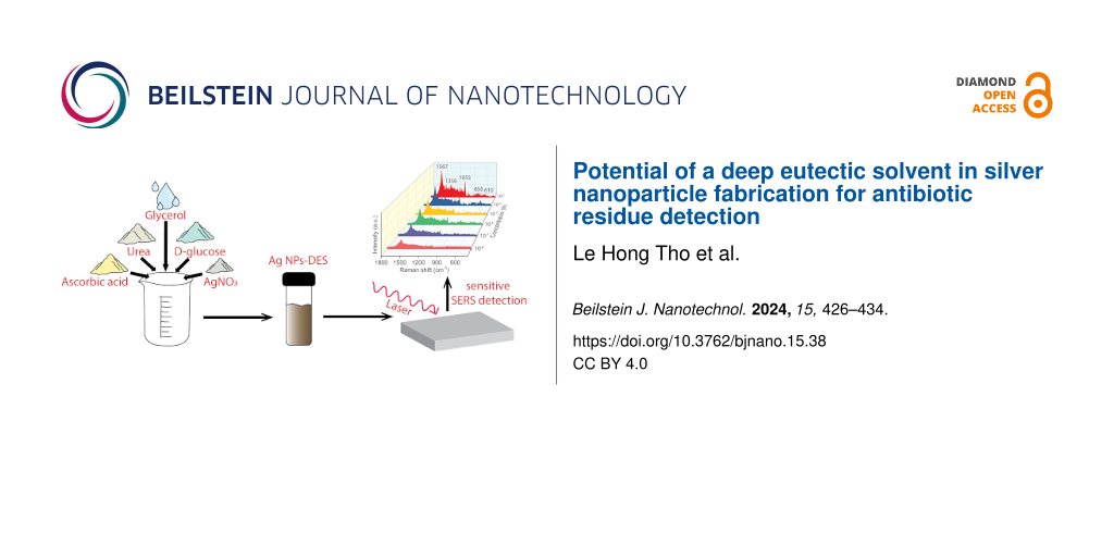

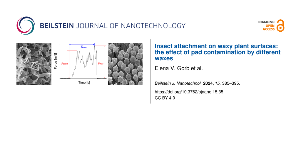
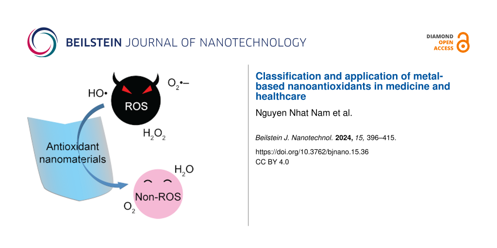
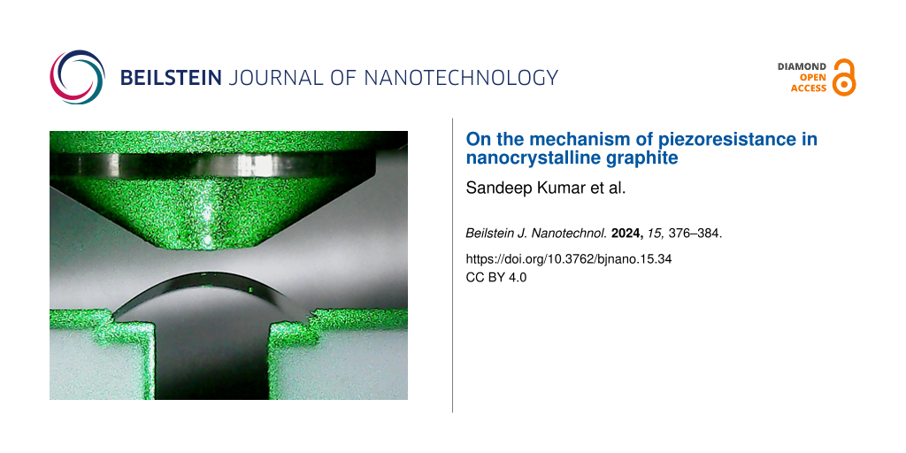
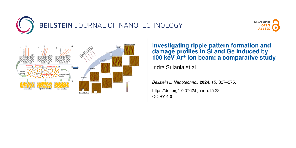
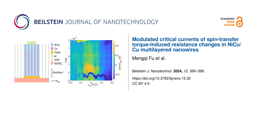


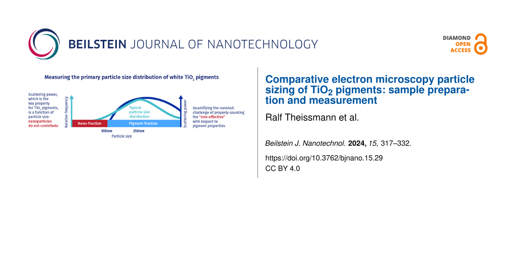
Figure 2 shows contact AFM topography images recorded at room temperature on the surface of the eutectic Ga–In–Sn melt with three AFM tips of different chemistries, namely SiOx, PtSi, and Au. Figure 2 also indicates the surface roughness Rq value for each topography image. We recorded the presented topography images in contact mode by setting and controlling the normal force to Fn = 2 nN and the sliding velocity to vs = 4 µm/s. Depending on the tip chemistry, we determined different roughness values ranging from Rq = 4.48 nm with a gold tip to Rq = 10.13 nm with a platinum silicide tip. This dependence on the tip chemistry likely originates from different capillary interactions between the eutectic Ga–In–Sn melt and the tips, where large capillary forces would result in a larger apparent topography.
![[2190-4286-13-72-2]](https://www.beilstein-journals.org/bjnano/content/figures/2190-4286-13-72-2.png?scale=2.0&max-width=1024&background=FFFFFF)
Figure 2: Contact AFM topography images recorded on the surface of eutectic Ga–In–Sn with (a) SiOx, (b) PtSi, and (c) Au AFM tips. We set the normal force to Fn = 2 nN and the scanning velocity to vs = 4 µm/s.
We can infer the occurrence of capillary interactions during the sliding of an AFM tip on the surface of the eutectic Ga–In–Sn melt from the traces of the normal and lateral forces plotted for both forward and backward directions as presented in Figure 3. There, the normal force plots show the normal force signal as controlled by the feedback loop in red color, while the normal force traces in blue and orange colors were calculated from the height traces in, respectively, the forward and backward direction by multiplying the height signal with the bending stiffness. We observe a hysteresis for both normal and lateral forces, which indicates a dragging force opposing the sliding motion of the tip. The observation of hysteresis for the lateral force is common on solid surfaces and corresponds to friction. In our case, we attribute the observed hysteresis of the lateral force to the resistance to pull and drag a meniscus at the tip–metallic liquid interface. In principle, this resistance corresponds to the interfacial tension of the tip and metallic liquid. The occurrence of hysteresis for the normal force is not as straightforward to explain. In our experiments, we can exclude the effect of crosstalk due to misalignment of the cantilever since we mounted each cantilever on the same alignment chip on the cantilever holder. We consider it more likely that the hysteresis of the normal force arises from a tilt between cantilever and the liquid surface.
![[2190-4286-13-72-3]](https://www.beilstein-journals.org/bjnano/content/figures/2190-4286-13-72-3.png?scale=2.0&max-width=1024&background=FFFFFF)
Figure 3: Typical (a–c) Fn- and (d–f) Fl-traces recorded in contact AFM mode on the surface of the eutectic Ga–In–Sn melt with (a, d) a SiOx tip, (b, e) a PtSi tip, and (c, f) an Au tip.
Figure 3 shows that the magnitude of the dragging force, that is, the sum of half-widths of the normal and lateral force hystereses, strongly depends on the tip chemistry. It is maximal for the PtSi tip and minimal for the Au tip. These preliminary results indicate that adhesion and capillary effects affect the tip–liquid contact. In particular, Figure 2 and Figure 3 indicate that the contact between SiOx and PtSi is rather inelastic. In a first attempt to characterize the interfacial tension between the surface of the eutectic Ga–In–Sn melt, we determined the adhesion force between the eutectic Ga–In–Sn melt and AFM tips of the abovementioned chemistry as a function of the temperature and the pulling velocity. Figure 4 summarizes these results. We do not observe any clear tendency for the adhesion force regarding temperature or pulling velocity for all presented cases. However, by taking the average of all adhesion force values for each tip, we find the following mean values and associated standard deviations: ![[Graphic 3]](https://www.beilstein-journals.org/bjnano/content/inline/2190-4286-13-72-i3.svg?max-width=637&scale=1.18182) = 6.46 ± 2.35 nN,
= 6.46 ± 2.35 nN, ![[Graphic 4]](https://www.beilstein-journals.org/bjnano/content/inline/2190-4286-13-72-i4.svg?max-width=637&scale=1.18182) = 7.77 ± 4.61 nN, and
= 7.77 ± 4.61 nN, and ![[Graphic 5]](https://www.beilstein-journals.org/bjnano/content/inline/2190-4286-13-72-i5.svg?max-width=637&scale=1.18182) = 29.19 ± 9.71 nN. Adhesion of a gold tip on the eutectic Ga–In–Sn melt is significantly larger than for SiOx and PtSi tips, which makes a clear distinction difficult. It is, however, noteworthy that the largest adhesion corresponds to the lowest dragging force, as illustrated in Figure 3. Above, we already discussed the meniscus formation at the tip–liquid interface. Here, we attempt to estimate the work of adhesion from the adhesion force according to the Johnson–Kendall–Roberts (JKR) model of adhesive contact [20], where Wad =
= 29.19 ± 9.71 nN. Adhesion of a gold tip on the eutectic Ga–In–Sn melt is significantly larger than for SiOx and PtSi tips, which makes a clear distinction difficult. It is, however, noteworthy that the largest adhesion corresponds to the lowest dragging force, as illustrated in Figure 3. Above, we already discussed the meniscus formation at the tip–liquid interface. Here, we attempt to estimate the work of adhesion from the adhesion force according to the Johnson–Kendall–Roberts (JKR) model of adhesive contact [20], where Wad = ![[Graphic 6]](https://www.beilstein-journals.org/bjnano/content/inline/2190-4286-13-72-i6.svg?max-width=637&scale=1.18182) and R is the tip radius. Strictly, this model applies to adhesive contact between elastic solids that form a wetting neck. Contact between two elastic solids is not provided in our experiments, and liquid flow will likely alter the calculated work of adhesion values. These values should thus be taken as rough estimates. With the manufacturer’s data for the tip radius (RSiOx = 7 nm and RPtSi = RAu = 25 nm), we calculate the following work of adhesion values:
and R is the tip radius. Strictly, this model applies to adhesive contact between elastic solids that form a wetting neck. Contact between two elastic solids is not provided in our experiments, and liquid flow will likely alter the calculated work of adhesion values. These values should thus be taken as rough estimates. With the manufacturer’s data for the tip radius (RSiOx = 7 nm and RPtSi = RAu = 25 nm), we calculate the following work of adhesion values: ![[Graphic 7]](https://www.beilstein-journals.org/bjnano/content/inline/2190-4286-13-72-i7.svg?max-width=637&scale=1.18182) = 195.83 ± 71.24 mN/m,
= 195.83 ± 71.24 mN/m, ![[Graphic 8]](https://www.beilstein-journals.org/bjnano/content/inline/2190-4286-13-72-i8.svg?max-width=637&scale=1.18182) = 65.95 ± 3.79 mN/m, and
= 65.95 ± 3.79 mN/m, and ![[Graphic 9]](https://www.beilstein-journals.org/bjnano/content/inline/2190-4286-13-72-i9.svg?max-width=637&scale=1.18182) = 247.76 ± 82.42 mN/m. Furthermore, the work of adhesion can be expressed according to
= 247.76 ± 82.42 mN/m. Furthermore, the work of adhesion can be expressed according to ![[Graphic 10]](https://www.beilstein-journals.org/bjnano/content/inline/2190-4286-13-72-i10.svg?max-width=637&scale=1.18182) = γa + γb + γa/b, where γa/b is the surface energy of the bodies a and b, and γa/b is the interfacial energy between the bodies a and b. The surface energy of the eutectic Ga–In–Sn melt at the melting point has been reported to be 587 mN/m [21], while published values for SiOx, PtSi, and Au are
= γa + γb + γa/b, where γa/b is the surface energy of the bodies a and b, and γa/b is the interfacial energy between the bodies a and b. The surface energy of the eutectic Ga–In–Sn melt at the melting point has been reported to be 587 mN/m [21], while published values for SiOx, PtSi, and Au are ![[Graphic 11]](https://www.beilstein-journals.org/bjnano/content/inline/2190-4286-13-72-i11.svg?max-width=637&scale=1.18182) = 53 mN/m [22],
= 53 mN/m [22], ![[Graphic 12]](https://www.beilstein-journals.org/bjnano/content/inline/2190-4286-13-72-i12.svg?max-width=637&scale=1.18182) = 1150–1300 mN/m depending on its orientation [23],
= 1150–1300 mN/m depending on its orientation [23], ![[Graphic 13]](https://www.beilstein-journals.org/bjnano/content/inline/2190-4286-13-72-i13.svg?max-width=637&scale=1.18182) = 1710 mN/m [24]. These values lead to the following results for the interfacial energy values of the different couples investigated in this work:
= 1710 mN/m [24]. These values lead to the following results for the interfacial energy values of the different couples investigated in this work: ![[Graphic 14]](https://www.beilstein-journals.org/bjnano/content/inline/2190-4286-13-72-i14.svg?max-width=637&scale=1.18182) = 0.44 N/m,
= 0.44 N/m, ![[Graphic 15]](https://www.beilstein-journals.org/bjnano/content/inline/2190-4286-13-72-i15.svg?max-width=637&scale=1.18182) = 2.2 N/m,
= 2.2 N/m, ![[Graphic 16]](https://www.beilstein-journals.org/bjnano/content/inline/2190-4286-13-72-i16.svg?max-width=637&scale=1.18182) ≈ 1.5 N/m. These values are, in part, significantly larger than the reported surface energy value of the eutectic Ga–In–Sn melt. Besides the limitation of the JKR model to describe our experiment, due to the meniscus flow of the eutectic Ga–In–Sn melt upon retraction, the adsorption of a thin water layer is likely to modify the surface energy of the liquid neck upon pulling and affect the above results. The analysis of the interfacial energy from AFM adhesion measurements is thus complicated by the absence of a suitable model and environmental effects.
≈ 1.5 N/m. These values are, in part, significantly larger than the reported surface energy value of the eutectic Ga–In–Sn melt. Besides the limitation of the JKR model to describe our experiment, due to the meniscus flow of the eutectic Ga–In–Sn melt upon retraction, the adsorption of a thin water layer is likely to modify the surface energy of the liquid neck upon pulling and affect the above results. The analysis of the interfacial energy from AFM adhesion measurements is thus complicated by the absence of a suitable model and environmental effects.
![[2190-4286-13-72-4]](https://www.beilstein-journals.org/bjnano/content/figures/2190-4286-13-72-4.png?scale=2.0&max-width=1024&background=FFFFFF)
Figure 4: Fad(T) plots for different pulling velocity values dZ/dt = 0.25–25 mm/s for (a) a SiOx tip, (b) a PtSi tip, and (c) a gold tip.
Alternatively, we determined the interfacial tension between AFM tips and the eutectic Ga–In–Sn melt from the approach part of force–distance curves recorded at different temperatures and approaching velocities. In this case, the tips penetrated the liquid sample to depths of several hundreds of nanometers. For this reason, we can neglect the effect of adsorbed water and assume an intimate contact between the tip material and the eutectic Ga–In–Sn melt. Also, unlike in adhesion experiments, where a pulled neck changes the geometry of the tip–liquid interface and may involve a flow of the liquid sample, the tip–liquid interface geometry is better defined upon penetration of the tip in the liquid. Figure 5 shows the temperature and velocity dependences of the interfacial energy between eutectic Ga–In–Sn melt and three AFM tips of SiOx, PtSi, and Au. For each dZ/dt-values, the temperature dependence of γ was fitted with the linear function γ(T) = γm + κ(T – Tm), where γm is interfacial at the melting point, κ is the temperature sensitivity of γ, and Tm is the melting point of eutectic Ga–In–Sn melt. The values of γm and κ are also shown as a function of dZ/dt in Figure 5. For all three tips, we observe slight increases in γ with the temperature. γ(T) significantly depends on the tip chemistry. γm and κ are lowest for PtSi tips and increase in the order of Au tip and SiOx tip. However, these values do not appear to depend on the approach velocity of the tips toward the liquid sample. Table 2 indicates the average values and ranges of γm and κ for the three different tip chemistries. Specifically, we find ![[Graphic 17]](https://www.beilstein-journals.org/bjnano/content/inline/2190-4286-13-72-i17.svg?max-width=637&scale=1.18182) = 230 mN/m and
= 230 mN/m and ![[Graphic 18]](https://www.beilstein-journals.org/bjnano/content/inline/2190-4286-13-72-i18.svg?max-width=637&scale=1.18182) = 3 mN/Km for SiOx,
= 3 mN/Km for SiOx, ![[Graphic 19]](https://www.beilstein-journals.org/bjnano/content/inline/2190-4286-13-72-i19.svg?max-width=637&scale=1.18182) = 110 mN/m and
= 110 mN/m and ![[Graphic 20]](https://www.beilstein-journals.org/bjnano/content/inline/2190-4286-13-72-i20.svg?max-width=637&scale=1.18182) = 2 mN/Km for Au, and
= 2 mN/Km for Au, and ![[Graphic 21]](https://www.beilstein-journals.org/bjnano/content/inline/2190-4286-13-72-i21.svg?max-width=637&scale=1.18182) = 68 mN/m and
= 68 mN/m and ![[Graphic 22]](https://www.beilstein-journals.org/bjnano/content/inline/2190-4286-13-72-i22.svg?max-width=637&scale=1.18182) = 0.8 mN/Km for PtSi.
= 0.8 mN/Km for PtSi.
![[2190-4286-13-72-5]](https://www.beilstein-journals.org/bjnano/content/figures/2190-4286-13-72-5.png?scale=2.0&max-width=1024&background=FFFFFF)
Figure 5: (a, d, g) Interfacial energy γ as a function of the temperature determined with dZ/dt = 0.25–25 mm/s; (b, e, h) interfacial energy at the melting point γm as a function of dZ/dt (the mean value of γm is indicated as a red dashed line and the range of values is indicated by two blue dashed lines); (c, f, i) temperature sensitivity κ of the interfacial energy as a function of dZ/dt (the mean value of κ is indicated as a red dashed line and the range of values is indicated by two blue dashed lines).
Table 2: Average values and range of γ and κ for PtSi, SiOx, and Au tip materials.
PtSi SiOx Au![[Graphic 23]](https://www.beilstein-journals.org/bjnano/content/inline/2190-4286-13-72-i23.svg?max-width=637&scale=1.0) [mN/m]
68
230
110
[mN/m]
68
230
110
![[Graphic 24]](https://www.beilstein-journals.org/bjnano/content/inline/2190-4286-13-72-i24.svg?max-width=637&scale=1.0) [mN/Km]
0.8
3
2
[mN/Km]
0.8
3
2
The surface tension of Ga–In–Sn eutectic liquid alloy at the melting point has been reported to be ![[Graphic 25]](https://www.beilstein-journals.org/bjnano/content/inline/2190-4286-13-72-i25.svg?max-width=637&scale=1.18182) = 587 mN/m, while its temperature sensitivity is κ* = −10 mN/Km [21]. This value for the surface energy is expected to be larger than the interfacial energy values determined in this work. However, the positive κ values in this work are unexpected and require a thorough discussion. In the following, we also discuss the effect of tip chemistry and oxide growth on the interfacial energy of Ga–In–Sn.
= 587 mN/m, while its temperature sensitivity is κ* = −10 mN/Km [21]. This value for the surface energy is expected to be larger than the interfacial energy values determined in this work. However, the positive κ values in this work are unexpected and require a thorough discussion. In the following, we also discuss the effect of tip chemistry and oxide growth on the interfacial energy of Ga–In–Sn.
The measurements presented here were performed in air. Thus, a thin native oxide layer, which may have grown upon heating, likely affected our measurements. Figure 6 and Table 3 show XPS results obtained on a drop of Ga–In–Sn eutectic liquid before and after heating in air at 100 °C for 3 h. The choice of this duration roughly corresponds to the time necessary to complete a series of AFM measurements.
![[2190-4286-13-72-6]](https://www.beilstein-journals.org/bjnano/content/figures/2190-4286-13-72-6.png?scale=2.0&max-width=1024&background=FFFFFF)
Figure 6: XPS results for the eutectic Ga–In–Sn melt (a) before and (b) after heating at 100 °C for 3 h.
Table 3: Surface chemical composition of Ga–In–Sn eutectic melt (a) before and (b) after heating for 3 h at 100 °C.
GametalFigure 6 and Table 3 show that, after heating, the oxygen concentration at the surface of the Ga–In–Sn eutectic liquid slightly decreased. Note that the 1s orbital of oxygen indicates the presence of carbonate groups at the surface of the Ga–In–Sn eutectic melt. Similarly, and not shown here, we observed a signal corresponding to the 1s orbital of carbon. We attribute these contributions (CO32−, C–C/C–H, and C–O) to contamination from the ambient. As mentioned above, we performed the XPS measurements on these liquid samples without prior Ar+-ion sputtering or further heating inside the vacuum chamber of the XPS instrument.
Given that these contributions arose from contamination by the ambient, we excluded them from our calculations of the surface chemical composition. Figure 6 shows that the surface oxide on the melt mainly consists of gallium and tin oxides, with a minor contribution from indium oxide. After heating at 100 °C for 3 h, this general trend was preserved.
Table 3 shows that after heating, the oxygen concentration at the surface of Ga–In–Sn eutectic liquid slightly decreased, that is, from 53.7 to 49.9 atom %. Moreover, the atomic fraction of gallium bound as native oxide increased from 23.2 to 27.0 atom %, while the atomic fractions of tin and indium bound as oxides (SnO or SnO2, and In2O3) did not significantly change. Given the atomic concentrations in Table 3, the native mixed surface oxide of the Ga–In–Sn eutectic liquid consists of GaO2–Sn2O3–In2O3 or (Ga0.8Sn0.14In0.06)O2. After heating, this concentration changed to (Ga0.84Sn0.10In0.06)O2. The enrichment of the surface oxide in gallium at the expense of oxygen may indicate that oxygen was brought into solution in the Ga–In–Sn bulk liquid during heating.
Further, we estimate the change of the surface oxide thickness based on the change of the ratio between Ganative oxide and Gametal. Before heating, we calculated this ratio to be 2.38, while after heating, we found 2.64. The slight increase in the Ganative oxide/Gametal ratio after heating indicates that the surface oxide thickness did not significantly increase if we consider the oxide enrichment in Ga. According to the manufacturer, the interaction depth of the XPS was approx. 10 nm. We detected metallic bonded Ga, In, and Sn; thus, we infer that the oxide layer was less than 10 nm thick. Thickness and composition of the surface oxide of a similar newly developed Ga–In–Sn-Zn liquid alloy have been characterized by TEM and XPS [25]. The authors reported on the effect of electron beam exposition time on the growth of a ZnGa2O4 layer. After 35 min irradiation, the oxide layer had grown from 2 nm to less than 5 nm. Besides this moderate growth, the authors observed the partial crystallization of the oxide layer during electron beam exposition. We measured the temperature dependence of the interfacial energy between Ga–In–Sn eutectic liquid and AFM tips by dipping the AFM tips inside a Ga–In–Sn liquid drop. The penetration depth of the tips was in the order of several hundreds of nanometers.
We did not observe any pop-in in the force–penetration curves that would indicate a sharp rupture of the oxide film. Such an observation required a higher sampling rate than used during the measurements. However, the experimental data points deviate from the linear fit function at penetration depth values below 50 nm (see Figure 4b,c). At low penetration depth values, the contact between tip and liquid may not be intimate yet, and the observed deviation from linearity in the Fn(δ) plots may correspond to a pre-tension effect of the interface. The penetration of the tip at larger depths is thus expected to be representative of the contact between nanoscopic asperities and metallic melt.
Furthermore, we estimated the chemical composition of the metallic melt below the oxide layer from the concentrations listed in Table 3. In the case of as-received Ga–In–Sn eutectic liquid, we find Ga55.38In28Sn16.62, while after heating, we find Ga56.75In24.61Sn18.64. Both compositions strongly deviate from the nominal composition of the alloy Ga78.8In13.2Sn8. These results hint at chemical segregations at the metallic liquid surfaces, whose net effect is reducing the surface tension of the liquid alloy (see discussion below).
To discuss the effect of tip chemistry and temperature on our results, it shall be convenient to remind the reader about the physical origin and the thermodynamic interpretation of surface and interfacial energies. The surface tension arises from the imbalanced bonding of atoms at the liquid–vapor interface. Interfacial atoms are attracted by atoms in the bulk liquid to experience a pulling force in the direction from the surface to the bulk of the liquid. This effectively results in the tendency of the system to minimize its interfacial area with vapor or a vacuum. Hence, the surface tension can be defined as the work to create a new unit area of surface reversibly. For a single component liquid, this translates as γ*A = Fs, where A is the surface area and Fs is the Helmholtz free energy of the surface. In the case of a multicomponent and single-phase liquid, this equality is reduced by chemical segregation at the surface, that is, ![[Graphic 26]](https://www.beilstein-journals.org/bjnano/content/inline/2190-4286-13-72-i26.svg?max-width=637&scale=1.18182) where µi is the chemical potential of the i-th component and Γi is its adsorption [26]. By neglecting the effect of surface segregation on the surface tension, the differential of the Helmholtz free energy of the surface can be written as dFs = γ*dA + Adγ* or
where µi is the chemical potential of the i-th component and Γi is its adsorption [26]. By neglecting the effect of surface segregation on the surface tension, the differential of the Helmholtz free energy of the surface can be written as dFs = γ*dA + Adγ* or ![[Graphic 27]](https://www.beilstein-journals.org/bjnano/content/inline/2190-4286-13-72-i27.svg?max-width=637&scale=1.18182) which allows for a correlation of the thermal sensitivity of the surface or interfacial tension
which allows for a correlation of the thermal sensitivity of the surface or interfacial tension ![[Graphic 28]](https://www.beilstein-journals.org/bjnano/content/inline/2190-4286-13-72-i28.svg?max-width=637&scale=1.18182) with the surface or interfacial entropy
with the surface or interfacial entropy ![[Graphic 29]](https://www.beilstein-journals.org/bjnano/content/inline/2190-4286-13-72-i29.svg?max-width=637&scale=1.18182) According to [27,28], the temperature sensitivity of the surface energy of simple metallic melts depends on the change of the cohesion energy with temperature and, thus, scales with their molar area and thermal expansion coefficient.
According to [27,28], the temperature sensitivity of the surface energy of simple metallic melts depends on the change of the cohesion energy with temperature and, thus, scales with their molar area and thermal expansion coefficient.
The surface tension of the eutectic Ga–In–Sn liquid at the melting point has been reported to ![[Graphic 30]](https://www.beilstein-journals.org/bjnano/content/inline/2190-4286-13-72-i30.svg?max-width=637&scale=1.18182) = 587 mN/m. Since the surface tension originates from the imbalanced bonding of atoms at the liquid–vapor interface [29], it shall be no surprise that the interfacial tension of the same liquid in contact with a solid is smaller since a solid surface also consists of atoms with unsaturated bonds that can minimize their energy by bonding with atoms from the liquid surface. Depending on the chemistry of the AFM tip, we find that a factor of two to eight reduces the interfacial energy compared to the surface energy. Figure 7 shows SEM images of the tips after measurements on the Ga–In–Sn eutectic liquid. Unlike the PtSi and Au tips, the SiOx tip in Figure 7 exhibits residues of the liquid alloy up to a height from the tip apex of h ≈ 200 nm, which corresponds to the penetration depth of the tip into the liquid alloy. Coincidently, we determined the largest interfacial tension value at the melting point of the liquid alloy for the same tip,
= 587 mN/m. Since the surface tension originates from the imbalanced bonding of atoms at the liquid–vapor interface [29], it shall be no surprise that the interfacial tension of the same liquid in contact with a solid is smaller since a solid surface also consists of atoms with unsaturated bonds that can minimize their energy by bonding with atoms from the liquid surface. Depending on the chemistry of the AFM tip, we find that a factor of two to eight reduces the interfacial energy compared to the surface energy. Figure 7 shows SEM images of the tips after measurements on the Ga–In–Sn eutectic liquid. Unlike the PtSi and Au tips, the SiOx tip in Figure 7 exhibits residues of the liquid alloy up to a height from the tip apex of h ≈ 200 nm, which corresponds to the penetration depth of the tip into the liquid alloy. Coincidently, we determined the largest interfacial tension value at the melting point of the liquid alloy for the same tip, ![[Graphic 31]](https://www.beilstein-journals.org/bjnano/content/inline/2190-4286-13-72-i31.svg?max-width=637&scale=1.18182) = 230 mN/m. The adhesion of melt residues at the SiOx tip can be attributed to the respective stabilities of the oxides at the tip and at the liquid surface, respectively. Their stability can be discussed based on their respective melting points and enthalpies of fusion ΔHfus and formation at T = 298.15 K,
= 230 mN/m. The adhesion of melt residues at the SiOx tip can be attributed to the respective stabilities of the oxides at the tip and at the liquid surface, respectively. Their stability can be discussed based on their respective melting points and enthalpies of fusion ΔHfus and formation at T = 298.15 K, ![[Graphic 32]](https://www.beilstein-journals.org/bjnano/content/inline/2190-4286-13-72-i32.svg?max-width=637&scale=1.18182) For amorphous SiO2, the following values were reported:
For amorphous SiO2, the following values were reported: ![[Graphic 33]](https://www.beilstein-journals.org/bjnano/content/inline/2190-4286-13-72-i33.svg?max-width=637&scale=1.18182) = 1726 K,
= 1726 K, ![[Graphic 34]](https://www.beilstein-journals.org/bjnano/content/inline/2190-4286-13-72-i34.svg?max-width=637&scale=1.18182) = 7.438 kJ/mol, and
= 7.438 kJ/mol, and ![[Graphic 35]](https://www.beilstein-journals.org/bjnano/content/inline/2190-4286-13-72-i35.svg?max-width=637&scale=1.18182) = −910.68 kJ/mol [30]. For Ga2O3, the literature reports
= −910.68 kJ/mol [30]. For Ga2O3, the literature reports ![[Graphic 36]](https://www.beilstein-journals.org/bjnano/content/inline/2190-4286-13-72-i36.svg?max-width=637&scale=1.18182) = 2080 K,
= 2080 K, ![[Graphic 37]](https://www.beilstein-journals.org/bjnano/content/inline/2190-4286-13-72-i37.svg?max-width=637&scale=1.18182) = 99.77 kJ/mol, and
= 99.77 kJ/mol, and ![[Graphic 38]](https://www.beilstein-journals.org/bjnano/content/inline/2190-4286-13-72-i38.svg?max-width=637&scale=1.18182) = −1090.85 kJ/mol [30]. Hence, it appears that Ga2O3 is significantly more stable than SiO2, and we suggest that upon penetrating the Ga–In–Sn eutectic melt, oxygen atoms at the tip surface react with Ga to form a solid Ga2O3 layer at the tip–melt interface. In this scope, the
= −1090.85 kJ/mol [30]. Hence, it appears that Ga2O3 is significantly more stable than SiO2, and we suggest that upon penetrating the Ga–In–Sn eutectic melt, oxygen atoms at the tip surface react with Ga to form a solid Ga2O3 layer at the tip–melt interface. In this scope, the ![[Graphic 39]](https://www.beilstein-journals.org/bjnano/content/inline/2190-4286-13-72-i39.svg?max-width=637&scale=1.18182) value determined in this work may have been increased by the presence of a solid Ga2O3 layer at the tip–melt interface. Our interpretation is supported by recent calculations of the surface energy of Ga2O3 in [31]. Depending on the surface orientation, a range of values between 0.6 N/m and 2.98 N/m has been reported.
value determined in this work may have been increased by the presence of a solid Ga2O3 layer at the tip–melt interface. Our interpretation is supported by recent calculations of the surface energy of Ga2O3 in [31]. Depending on the surface orientation, a range of values between 0.6 N/m and 2.98 N/m has been reported.
![[2190-4286-13-72-7]](https://www.beilstein-journals.org/bjnano/content/figures/2190-4286-13-72-7.png?scale=2.0&max-width=1024&background=FFFFFF)
Figure 7: SEM images of the AFM tips used to collect the results presented in Figure 2: (a, d) SiOx tip, (b, e) Au tip, and (c) PtSi tip.
The values of ![[Graphic 40]](https://www.beilstein-journals.org/bjnano/content/inline/2190-4286-13-72-i40.svg?max-width=637&scale=1.18182) and
and ![[Graphic 41]](https://www.beilstein-journals.org/bjnano/content/inline/2190-4286-13-72-i41.svg?max-width=637&scale=1.18182) determined in this work are significantly lower than
determined in this work are significantly lower than ![[Graphic 42]](https://www.beilstein-journals.org/bjnano/content/inline/2190-4286-13-72-i42.svg?max-width=637&scale=1.18182) and
and ![[Graphic 43]](https://www.beilstein-journals.org/bjnano/content/inline/2190-4286-13-72-i43.svg?max-width=637&scale=1.18182) Due to its chemical inertness, reactivity between PtSi and eutectic Ga–In–Sn melt can be ruled out. Also, reactions between gold and the constituting elements of the metallic melt are not expected. Solid gallium has very poor solubility for gold, and Ga forms a eutectic with AuGa2 with a melting temperature of 491 °C. We thus exclude its formation during our experiment. However, the Ga-rich melt has a large solubility for Au.
Due to its chemical inertness, reactivity between PtSi and eutectic Ga–In–Sn melt can be ruled out. Also, reactions between gold and the constituting elements of the metallic melt are not expected. Solid gallium has very poor solubility for gold, and Ga forms a eutectic with AuGa2 with a melting temperature of 491 °C. We thus exclude its formation during our experiment. However, the Ga-rich melt has a large solubility for Au.
For this reason, we assume that a small amount of gold dissolved in the metallic melt investigated here. However, the dissolution of Au should be small since it is thermally activated. In the current study, we could not observe any degradation of the Au tip nor measure traces of Au in liquid Ga–In–Sn. The phase diagram of the Au–In alloy system is similar to that of Au–Ga. However, the difference is that the eutectic formed between In and AuIn2 lays at 156 °C, higher than the maximum temperature applied during our measurements. Finally, the Au–Sn system shows no solubility of Au in Sn and exhibits a eutectic between AuSn4 and Sn at 211 °C. A reaction between Au and Sn can thus be ruled out for our experimental conditions.
In [23], the authors calculated the surface energy of gold nanoparticles of different shapes. The authors found that the surface energy sharply increases for diameters smaller than 5 nm for spherical particles. In our experiments, the Au tip apex can be considered a sphere with a radius R = 25 nm. According to [23], the surface energy of the gold tip can be assumed to be in the range of ![[Graphic 44]](https://www.beilstein-journals.org/bjnano/content/inline/2190-4286-13-72-i44.svg?max-width=637&scale=1.18182) = 1.15–1.30 J/m2. The surface energy of stochiometric PtSi(010) was calculated as a function of the number of (010) planes below the surface [24]. A slight decrease in surface energy was observed upon increasing the number of planes. For a supercell consisting of 25 (010) planes, the authors in [24] calculated the surface energy of PtSi,
= 1.15–1.30 J/m2. The surface energy of stochiometric PtSi(010) was calculated as a function of the number of (010) planes below the surface [24]. A slight decrease in surface energy was observed upon increasing the number of planes. For a supercell consisting of 25 (010) planes, the authors in [24] calculated the surface energy of PtSi, ![[Graphic 45]](https://www.beilstein-journals.org/bjnano/content/inline/2190-4286-13-72-i45.svg?max-width=637&scale=1.18182) = 1.71 J/m2. It is thus remarkable that the higher the surface energy of the tip material, the lower the interfacial energy between the tip and the Ga–In–Sn eutectic melt becomes. This result is so far expected as forming a tip–liquid interface rids areal parts of the tip–vapor and the Ga–In–Sn eutectic melt–vapor interfaces and, thus, decreases the energy of the system. The larger the individual free surface energies, the larger the energetic gain upon the formation of an interface.
= 1.71 J/m2. It is thus remarkable that the higher the surface energy of the tip material, the lower the interfacial energy between the tip and the Ga–In–Sn eutectic melt becomes. This result is so far expected as forming a tip–liquid interface rids areal parts of the tip–vapor and the Ga–In–Sn eutectic melt–vapor interfaces and, thus, decreases the energy of the system. The larger the individual free surface energies, the larger the energetic gain upon the formation of an interface.
Above, we have related the temperature sensitivity of the surface energy κ to the surface entropy Ss. For most liquids, the value κ is negative, owing to an increase in entropy at higher temperatures. This entropy increase can be rationalized by decreasing the coordination number at a liquid surface at higher temperatures. However, a few exceptions have been observed to take positive values. For pure silver, a positive temperature sensitivity has been observed in the temperature range between 1200 and 1500 K, which was associated with oxygen [10]. In this case, oxygen acts as a surface-active element that leads to chemical segregations at the surface. A similar phenomenon was reported for Ga–Bi liquid alloys, in which case a positive temperature sensitivity κ has been observed to increase with the bismuth content. The surface enrichment also explained this result in bismuth, which exhibits a lower surface tension than gallium. Our XPS results also hint at an enrichment in tin and indium at the surface of the Ga–In–Sn eutectic alloy. The surface tension of tin and indium at their melting point is ![[Graphic 46]](https://www.beilstein-journals.org/bjnano/content/inline/2190-4286-13-72-i46.svg?max-width=637&scale=1.18182) = 689 mN/m and
= 689 mN/m and ![[Graphic 47]](https://www.beilstein-journals.org/bjnano/content/inline/2190-4286-13-72-i47.svg?max-width=637&scale=1.18182) = 562 mN/m, while for pure gallium, the literature reports
= 562 mN/m, while for pure gallium, the literature reports ![[Graphic 48]](https://www.beilstein-journals.org/bjnano/content/inline/2190-4286-13-72-i48.svg?max-width=637&scale=1.18182) = 713 mN/m [32]. Thus, negative κ values can be explained based on chemical surface segregations. In this line, we suggest that the effect of tip chemistry on κ can be rationalized based on the solubility or reaction of the tip material with the metallic melt. We have already explained the high interfacial energy between SiOx and the Ga–In–Sn eutectic melt based on the reaction of oxygen atoms from SiOx with gallium atoms. This reaction is likely to be thermally activated, which would also explain the increase of the interfacial energy with the temperature based on the growth of an interfacial oxide layer. We suggest that tip material comes into solution in the Ga–In–Sn eutectic melt for the gold and platinum silicide tips. Though not verified here, we speculate that the partial and thermally activated solubility ot he tip materials in our metallic melt would form a segregation layer and increase the interfacial tension.
= 713 mN/m [32]. Thus, negative κ values can be explained based on chemical surface segregations. In this line, we suggest that the effect of tip chemistry on κ can be rationalized based on the solubility or reaction of the tip material with the metallic melt. We have already explained the high interfacial energy between SiOx and the Ga–In–Sn eutectic melt based on the reaction of oxygen atoms from SiOx with gallium atoms. This reaction is likely to be thermally activated, which would also explain the increase of the interfacial energy with the temperature based on the growth of an interfacial oxide layer. We suggest that tip material comes into solution in the Ga–In–Sn eutectic melt for the gold and platinum silicide tips. Though not verified here, we speculate that the partial and thermally activated solubility ot he tip materials in our metallic melt would form a segregation layer and increase the interfacial tension.
留言 (0)