
記住我

Total hip arthroplasty (THA) is currently the best treatment option for patients with end-stage hip osteoarthritis secondary to developmental dysplasia of the hip (DDH). Many scholars1-3 believed that the acetabulum reconstruction with high hip rotation center technique could simplify the operation, increase the coverage rate of acetabular prosthesis and the initial stability of the acetabular cup. However, the upward migration of the hip rotation center will increase the biological stress of the hip joint and the wear rate of the prosthesis interface, coupled with complications such as lower limbs length discrepancy, impingement, gluteus medius muscle fatigue, dislocation and so on. Currently, it is advocated to restore hip rotation center anatomically in THA, due to anatomical restoration can recover the balance between prosthesis and soft tissue, thus reducing the wear rate and prosthesis loosening4-6.
However, it is difficult to restore the hip rotation center during the operation, due to the complicated changes of acetabular morphology. The acetabular pathomorphology characters of DDH mainly present as follows: the acetabulum is shallow and flat with false socket formation, the acetabular anteversion and inclination are increased, the hip rotation center migrates toward cephalic and lateral direction, a large number of osteophytes proliferate as well as the anterior and posterior wall of the acetabulum are poorly developed. Many methods7-9, such as, template method, concentric circle method of the healthy side, Ranawat method, Pierchon method and Pagnano method, etc., have been used to locate the rotation center of the hip joint. However, the above methods were all determined by two-dimensional image of the pelvis and could only be used for preoperative plan and postoperative evaluation, which were of little value to guide intraoperative location of the hip rotation center. Andriacchi and Strickland10 estimated that the hip rotation center would lie 1.5 ± 2 cm directly distal to the midpoint of a line connecting the antero-superior iliac spine and the pubic symphysis in the frontal plane. Kirkwood et al.11 also agreed with the above point of view. Although these methods took the hip rotation center as three-dimensional (3D) concept into consideration, however, they relied on accurate palpation of bony landmarks and estimation of the distance between them to locate the hip joint center, which had limited value to instruct surgeons to locate the hip rotation center in the operation. Dardenne et al.12 reported that the hip center could be determined by the Pivot method accurately in computer assisted (or navigated) orthopedic surgery. Computer-assisted technology could promote the accuracy of locating the hip rotation center, but it needs high requirements of devices and technology, which is difficult to be popularized. Sakellariou et al.4 reported that intraoperative recognition of the inferior rim of the acetabulum and identification of the acetabular notch were of paramount importance which were useful to identify the true acetabulum and restore the hip joint center. However, these two anatomical landmarks could only be referenced intraoperatively, the relationships between the acetabular center and these two landmarks were obscure. There is still lack of an intuitive and operable method for surgeons to locate the hip rotation center in THA. In our previous study13, it was proved that the morphology of the acetabular notches and Harris fossa could be restored and recognized by removing the covered osteophytes in all Crowe types of DDH, which facilitated restoring the rotation center exactly. We found there was a constant relationship between the acetabular center and Harris fossa, as well as acetabular notches, which could be used to locate the acetabular center. However, it is difficult to recognize the morphology of the acetabulum and Harris fossa and locate the acetabular center rapidly, especially for orthopedists who lack experience.
With the rapid development of 3D printing technology, the individual life-size models allow surgeons to simulate operations and perform precise treatment, as well as improve outcomes14-16. 3D printed models of patients' complicated anatomical sites enabled surgeons to have better understanding of the topographic anatomy and make personalized operative planning, including preoperative design, intraoperative guidance, and surgeon training14. Mishra et al.15 reported the 3D printing technique was useful in managing complex fractures by accurate reduction and placement of implants, reduction of surgical time and with better results. Hughes et al.16 reconstructed the acetabulum effectively for three complex second-stage hip revision cases by simulating the sizes and positions of the acetabular cup, augment, buttress, and cage on 3D printed life-size models. Wang et al.17 reported the 3D printing model and simulated operation improved trainees' performance compared with the traditional surgical live teaching method, which was helpful for trainees who were already in practice and not experienced enough to have mastered DDH THA surgical techniques.
Therefore, in this study, a method was developed to restore the hip rotation center by simulating operations on a 3D print model, which helped surgeons to locate the acetabular center in DDH THA effectively and rapidly. The purpose of this study was: (i) to introduce a new method to restore the morphology of acetabular notches and Harris fossa and hip rotation center with the assistance of 3D printing technique; (ii) to evaluate the clinical and radiological outcomes of patients who underwent this procedure; and (iii) to discuss the advantages of this new method compared with other techniques.
Materials and Methods Inclusion and Exclusion CriteriaThe inclusion criteria were: (i) hip end-stage osteoarthritis (OA Tonnis III stage) due to DDH (Crowe type I to IV); (ii) patients who underwent THA with the assistance of 3D printing technique; (iii) the muscle strength of the affected limb was normal, age range was from 30 to 75 years; (iv) the hip joint pain affected daily life and work; and (v) patients with complete data during the hospital and the follow-up periods. The exclusion criteria were: hip trauma history or combined with other hip diseases.
Patient InformationThis study involved 17 patients (21 hips) who underwent primary cementless THA from March 2013 to July 2018. The 17 patients included four men (five hips) and 13 women (16 hips). The average age is 58.00 ± 8.12 years (range from 45 to 71 years). The average of body mass index is 25.70 ± 3.33 kg/m2 (range from 18.55 to 31.63 kg/m2). The average preoperative lower limbs length discrepancy (LLD) was 2.43 ± 1.07 cm (range from 0.5 to 4.0 cm), in which seven patients' LLD is below 2 cm, 14 patients' LLD between 2–4 cm. There were three hips of Crowe type I, seven hips of Crowe type II, nine hips of Crowe type III, two hips of Crowe type IV.
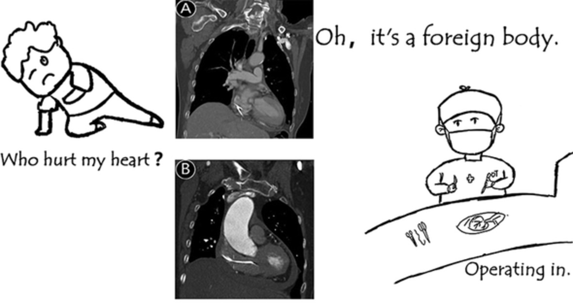
The preoperative pelvic radiographs usually displayed that the acetabulum was superficial flat, the femoral head displaced toward outside and upward, the Shenton's line was interrupted, the joint space was narrow and the surface of Harris fossa was covered with osteophytes (Fig. 1A). The false socket and osteophytes could be displayed clearly in a 3D computed tomography (CT) image (Fig. 1B). Although the Harris fossa was covered with osteophytes, it could be judged and discovered by cross sectional CT image (Fig. 1B). The Harris Hip Score (HHS) was used to evaluate the preoperative hip joint function.

Preoperative imageological examinations. (A, B) Preoperative X-ray and 3D-CT showed the complicated pathological changes of end-stage hip osteoarthritis secondary to Crowe type III DDH. (C) Preoperative horizontal CT scan showed the Harris fossa existed and covered with osteophytes.
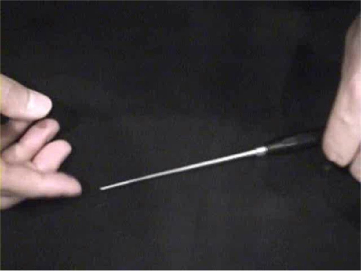
Simulated Operation and Preoperative Planning for Restoring Hip Rotation Center on 3D Printing ModelAn individual life-size model was printed by 3D printing machine (Arigin 3DM400, Shanghai Arigin medical technology, Shanghai, China) using polylactic acid (PLA) material, based on patients' pelvis 3D CT data (Fig. 2A). The Harris fossa was covered with osteophytes and restored its morphology by removing the osteophytes (Fig. 2B). The anterior and posterior acetabular notches were recognized and the perpendicular bisector of acetabular anterior and posterior notches' line was marked. The acetabular center was located at 25–31 mm (mean 28.7 mm, depended on the size of the acetabulum) above the intersection point of the perpendicular bisector and acetabular anterior and posterior notches' line (Fig. 2C)13, which could also be located by our self-developed acetabular center locator (Fig. 2D). During the process of acetabulum reaming, the anteversion was controlled in the range of 15° ± 10 °, while the inclination was 40° ± 10°, and the depth was the bottom of Harris fossa. Reaming was at concentric circles from small to large, aiming at the acetabular center (Fig. 2E). The final reaming size was determined by the criterion that the anterior and posterior wall had sufficient clamping force to obtain good initial stability of the test cup (Fig. 2F). The bone defect above the cup was filled with bone wax (Fig. 2G). The size of cup and bone defect was recorded.

The simulated operation on 3D print model. (A) 3D print model. (B) Recognizing and restoring Harris fossa. (C) Locating the acetabular center. (D) Locating the acetabular center by ACL. (E) Reaming the acetabulum. (F) Installing the acetabular cup. (G) Filling and measuring the bone defect by bone wax. 3D, three-dimensional; ACL, acetabular center locator.
The size of bone defect was measured by the bone wax method. We only measured the area of contact surface between bone wax and cup, which was vital to determine bone ingrowth (Fig. 3A,B). The surface of bone wax which needed to be measured was covered with gauze precisely (Fig. 3C). The gauze was removed from the bone wax and laid flat. The gauze was placed in the area surrounded by two rulers which were mutually perpendicular (Fig. 3D). A picture was taken by digital camera (SONY DSC-T90, 10.2 MP, SONY Company, Tokyo, Japan). The pictures were inputted into Photoshop software. The boundary of gauze and rulers were marked respectively. The size of the selected zone could be expressed by the pixels. The actual area of gauze could be calculated by this method: the pixels of the gauze zone divided the pixels of the ruler zone and then multiplied the actual area of the ruler zone, such as (434 × 147) divided by (737 × 733) multiplied by (10 ×10) cm2.

Bone defect measurement using bone wax method. (A, B) Bone wax. (C) Using the gauze to cover the surface of bone wax needed to be measured. (D) Laying the gauze flat and placing it in the measured region. (E) Measuring the area of gauze by Photoshop software.
Surgical Technique Anesthesia and PositionThe patients underwent general anesthesia and were placed in the lateral decubitus position. Anterior and posterior surgical hip supports were used to make the pelvis completely rigid and perpendicular to the surgical bed.
Approach and ExposureThe posterolateral approach was applied for all patients. The contracture soft tissue around the hip joint was released completely, paying much attention to protect the sciatic nerve and gluteus medius femoral insertion. The elongated and thickened joint capsule was resected and the osteophytes around the acetabulum were removed completely. The true acetabulum could be displayed clearly thereafter (Fig. 5A). The morphology of Harris fossa was restored by removing the covered osteophytes (Fig. 5B). The acetabular anterior and posterior notches were recognized and the perpendicular bisector of acetabular anterior and posterior notches' line was marked.
Placement of Prosthesis and Acetabular ReconstructionThe acetabular center was located at 25–31 mm (mean 28.7 mm, depended on the size of the acetabulum) above the intersection point of the perpendicular bisector and acetabular anterior and posterior notches' line13 (Figs 4A, 5C). During the process of acetabular reaming, the anteversion was controlled in the range of 15° ± 10 °, while the inclination was 40° ± 10°, and the depth was the cortical bone of Harris fossa's bottom. Concentric circles were reamed from small to large, aiming at the acetabular center (Fig. 5D). The final reaming size was determined by the criterion that the anterior and posterior wall had sufficient bone and clamping force to obtain good initial stability of the test cup (Figs 4B,5E). The reconstruction methods of bone defect were determined according to the results of simulated operations. The size of bone defect was measured again by the bone wax method. Autograft cancellous bone granules from the trimmed femoral head were used to provide adequate superolateral coverage of the cup only when acetabular bone defect was >10% (Fig. 5F). The cementless press-fit acetabular prosthesis was implanted to obtain good initial stability, although additional screws were applied if required.

Illustration of the methods of locating the acetabular centers and installing the acetabular cup. (A) Illustration of the method of locating the acetabular center. The acetabular center was located at 28.7 mm on average above the intersection point of the perpendicular bisector and acetabular anterior and posterior notches' line. (B) Illustration of the method of installing the acetabular cup. The acetabular cup was installed stably on the basis of concentric circles reaming which was aimed at the acetabular center.

The process of restoring hip rotation center in THA. (A) Exposing the acetabulum. (B) Recognizing and restoring Harris fossa. (C) Locating the acetabular center. (D) Reaming the acetabulum. (E) Installing acetabular test model. (F) Installing acetabular prosthesis and impaction bone graft.
Postoperative ManagementAntibiotics were given for infection prophylaxis within 24 h. Anticoagulants were used to prevent deep vein thrombosis for 5 weeks. Ankle and quadriceps contraction exercises were started on the first day after operation. Patients were made to bear weight under the assistance of crutches until 4–6 weeks, partial weight bearing until 12 weeks, then to fully weight bearing thereafter. Patients were followed up clinically and radiologically at 0 week, 6 months and yearly thereafter.
Outcome MeasuresThe HHS was used to evaluate the preoperative and postoperative function of hip joint. Radiological assessment was performed on the pelvis plain radiograph (Fig. 6).
Harris Hip Score (HHS)The HHS was used to evaluate the recovery of hip function in an adult population. The HHS score system mainly includes four aspects, such as, pain, function, absence of deformity and range of motion. The score standard had a maximum of 100 points. A total score less than 70 is considered a poor score, 70 ~ fair, 80 ~ is good and 90 ~ excellent.
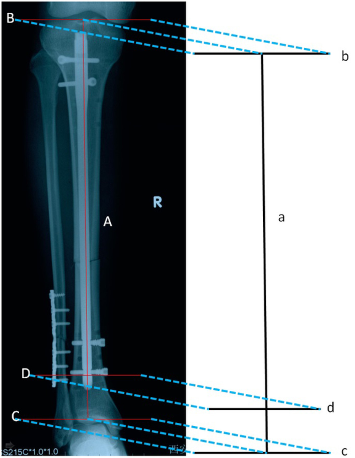
The Vertical and Horizontal DistanceThe vertical distance refers to the distance between the hip rotation center and the inter-teardrop line on the pelvis plain film. The horizontal distance refers to the distance between the hip rotation center and the ipsilateral teardrop on the pelvis plain film. Both the vertical distance and horizontal distance were used to assess the efficacy of restoring hip rotation center and acetabular cup migration.
Radiological Acetabular Prosthesis LooseningThe following radiological changes indicate acetabular prosthesis loosening: (i) the width of continuous radio transmittance area between bone and acetabular prosthesis is greater than or equal to 2 mm; (ii) the horizontal or vertical migration of acetabular prosthesis is greater than or equal to 5 mm; the rotation of acetabular prosthesis is greater than or equal to 4 mm.
Statistical AnalysisAll statistical analyses were performed by using SPSS software for Windows (version 19.0; SPSS, Chicago, IL, USA). Continuous variables were presented as means and ranges and categorical variables as frequencies. The 2-sided paired T test was used for comparison between preoperative and postoperative hip rotation center data measurement on pelvis plain films, bone defect area and HHSs. Intraclass correlation coefficient (ICC) was used to analyze the agreement between the size of the cup chosen on the basis of preoperative planning and the actual size in the operation. A P value <0.05 was considered statistically significant.
Results General ResultsAll 17 patients were available for clinical and radiological follow-up and an average follow-up time was 18.35 ± 6.86 months (range, 12–36 months).
Clinical AssessmentThe size of bone defect and reaming acetabulum, as well as the location of the acetabular center in the THA had high consistency the simulated operations on the 3D print model. The mean sizes of bone defect in simulated operations and THA were 4.58 ± 2.47 cm2 and 4.55 ± 2.57 cm2 respectively. There was no significant difference statistically between the sizes of bone defect in simulated operations and the actual sizes of bone defect in THA (t value: 0.03, P value: 0.97). The sizes of the acetabular cup of simulated operations on 3D print models showed a high rate of coincidence with the actual sizes in the operations (ICC value: 0.930). The measurement results of the bone defect area and cup size are shown in Table 1.
TABLE 1. The measurement results of bone defect area and cup size Patient No. Gender (male/female) Age (year) Crowe type Preoperative plan cup size Preoperative plan bone defect area (cm2) Intraoperative cup size Intraoperative bone defect area (cm2) 1 F 48 II(L) 48(L) 3.67(L) 48(L) 2.99(L) 2 M 65 II(R) 48(R) 4.40(R) 50(R) 4.62(R) 3 F 64 II(L) 48(L) 3.97(L) 48(L) 3.77(L) 4 M 71 III(L) 54(L) 10.96(L) 58(L) 11.81(L) 5 F 53 III(L) 46(L) 4.94(L) 48(L) 5.12(L) II(R) 46(R) 3.62(R) 46(R) 3.51(R) 6 F 53 II(L) 48(L) 3.69(L) 48(L) 3.51(L) 7 M 49 I(R) 50(R) 3.16(R) 50(R) 3.25(R) 8 F 50 III(L) 46(L) 5.35(L) 48(L) 5.56(L) 9 F 61 I(R) 52(R) 3.17(R) 52(R) 3.25(R) 10 F 68 II(L) 50(R) 4.47(L) 50(L) 4.42(L) III(R) 50(L) 6.87(R) 50(R) 6.90(R) 11 F 53 I(R) 48(R) 2.11(R) 48(R) 1.98(R) 12 F 53 IV(L) 44(R) 0(L) 44(L) 0(L) IV(R) 44(L) 0(R) 44(R) 0(R) 13 M 65 II(L) 48(R) 3.56(L) 50(L) 3.86(L) III(R) 48(L) 6.96(R) 48(R) 5.72(R) 14 F 61 III(R) 46(R) 5.36(R) 46(R) 5.31(R) 15 F 45 III(R) 46(R) 6.42(R) 46(R) 6.52(R) 16 F 69 III(R) 48(R) 6.69(R) 48(R) 6.56(R) 17 F 58 III(R) 48(R) 6.81(R) 50(R) 6.98(R)The average HHS of the patients was improved from pre-operation (38.33 ± 6.07) to the last follow-up (88.61 ± 3.44), including 12 excellent hips, eight good hips and one fair hip, the difference was statistically significant (t = 33.03, P < 0.05).
Radiological AssessmentThe average preoperative vertical distance of the hip rotation center on the pelvic radiographs was (40.48 ± 8.42) mm, the average postoperative one was (15.12 ± 1.25) mm; the average preoperative horizontal distance of hip rotation center on the pelvic radiographs was (41.49 ± 5.17) mm, and the average postoperative one was (32.49 ± 2.83) mm. The difference between the preoperative and postoperative vertical and horizontal distances of hip rotation center was statistically significant (t = 13.65, 6.99, P < 0.05).
ComplicationsNo revision was needed in all 17 cases. No patient had infection, hip dislocation, symptomatic deep vein thrombosis and other complications. Two patients had a slight limp.
Discussion Restoration of Hip Rotation CenterIt is still a challenge for orthopedists to restore hip rotation center anatomically in primary THA for patients with DDH, due to complicated acetabular changes4, 18. It has been widely accepted and advocated that acetabular prosthesis should be installed anatomically and the hip rotation center should be restored19-21. However, there is still a lack of a simple, intuitive and operable method to locate the hip rotation center during the operation up to now. Therefore, we developed a new method to restore the rotation center exactly and easily by recognizing and restoring Harris fossa and acetabular notches, which could be used to locate the acetabular center, with the assistance of simulating operations on 3D printed models. Our results demonstrated there was a high rate of occurance in the sizes of the acetabular component and the bone defect between preoperative planning on the 3D print model and THA. Compared with preoperative position, the hip rotation center was restored anatomically after the surgery.
In this study, we found Harris fossa always existed, even in cases of Crowe type II and III, which could be judged and was discoverable by a preoperative acetabulum CT scan. The acetabulum often presented as a dish shape and shell shape in Crowe type II and III, while the Harris fossa presented as a closed shape and triangle shape correspondingly. The acetabulum was filled with a large number of osteophytes, which covered the Harris fossa. During the operation, the Harris fossa could be restored by the following procedures: (i) exposing and recognizing the acetabulum and Harris fossa by removing the osteophytes. The Harris fossa was situated in the inferior part of the acetabulum, as well as in the middle of anterior and posterior wall of the acetabulum. (ii) Finding out the latent gap of Harris fossa by the following two methods. One method was to use a small osteotome to hit the middle part of Harris fossa, then a sense of breakthrough could be obtained. The other one was using a small flat nerve dissector to insert into the gap from the lowest part of the Harris fossa. (iii) Restoring the Harris fossa's morphology by using the Kerrison rongeur to remove the surface cortex bone to expose the whole outline. Once the morphology of Harris fossa was restored, there were two methods which helped to locate the acetabular center. The first was to utilize the relationship between the acetabular center and Harris fossa, as well as acetabular notches. The acetabular center was located at 25–31 mm (mean 28.7 mm, depended on the size of the acetabulum) above the intersection point of acetabular anterior and posterior notches' line and its perpendicular bisector. The second method was to use our self-developed acetabular center locator. We used this method to locate acetabular center in all DDH patients, whose hip rotation center could be restored exactly according to the assessment of postoperative X-rays (Fig. 6).

Postoperative X-ray showed the hip rotation center was restored anatomically.
Measurement of Acetabular Bone DefectThe reconstruction of the acetabular bone defect in THA was important because it affects the initial stability of the acetabular prosthesis21. The size of the acetabular bone defect determined the management of ways for reconstruction. Some scholars22, 23 reported the acetabular bone defect could be measured by imageological technology. However, there is still lack of an effective method to measure the bone defect in the operation. Here we present a solution to the measurement of acetabular bone defect accurately in THA by using bone wax. The bone wax is easy to reshape and adapt to an irregular bone defect. The curved surface of bone defect could be transformed into a flat area by using the gauze to cover the surface of the bone wax. The boundary of irregular gauze could be outlined easily in Photoshop software. This method realized precise measurement of the bone defect area.
Value of 3D Printing TechnologyPrevious studies have reported 3D printing simulated operations improved the accuracy and safety of orthopedic surgeries24. Huang et al.25 demonstrated that 3D printing technology increased the predictability, accuracy and reliability of both-column acetabular fractures reduction. Wang et al.26 reported that, compared with CT images or humerus-subtracted volume renderings, the 3D-printed model was able to represent the glenoid bony morphology accurately and clearly which facilitated shoulder surgeons to perform preoperative planning. A double-blinded randomized clinical trial indicated that osteotomy simulation on the 3D-print pelvis models for DDH patients increased the success rate of the operation and shortened surgery time, as well as promoted postoperative recovery27. Xu et al.28 recommended the use of the 3D print model before THA in DDH patients due to better preoperative planning and intraoperative orientation, as well as surgical outcomes. Our study demonstrated high agreement between the size of the acetabular cup and bone defect of simulated operations on 3D print models and the actual size used in the operations.
LimitationsOur study has several limitations. First, it was an independent study, there was no control group and the sample size was small. Second, the elastic attribute of 3D print model is not like bone, resulting in the errors between the simulated and intraoperative option of the acetabular cup size chosen. Finally, we only measured the contact interface area of bone defect, however, the bone defect was a 3D concept.
ConclusionsThe Harris fossa and acetabular notches are the important anatomical landmarkers which help to locate the acetabular center in THA. The application of 3D printing technology facilitates orthopedists to recognize the morphology of Harris fossa and acetabular notches, locate the acetabular center and restore the hip rotation center rapidly and accurately.
Ethics Approval and Consent to ParticipateThis study was approved by the Ethics Committee on Human Research of the First Affiliated Hospital of Bengbu Medical College, and informed consent was obtained from all involved patients.
Consent to PublishThis study was well understood and agreed by all the enrolled patients, which was recorded in the consent for publication.
留言 (0)